Dumping and loading persistent parameters to and from a file
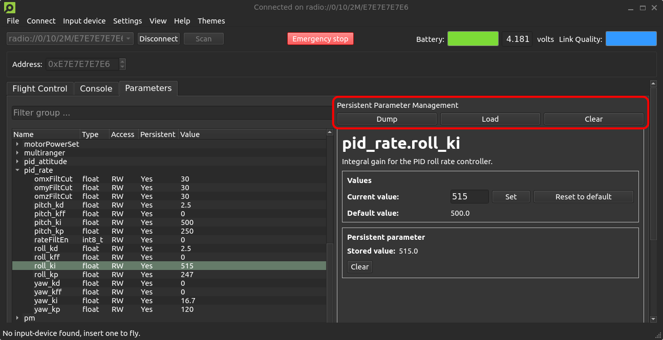
We have a small quality-of-life update that will allow users to dump and load persistent parameters to and from a file that has recently been merged #PR443 and #PR706. A new persistent parameter management area is introduced to the parameters tab of the client, with buttons for dumping and loading persistent parameters, as well as clearing all stored persistent parameters from the Crazyflie. The persistent parameters are stored in .yml format, allowing for manual editing if desired. If you have any improvement suggestions please drop us a comment!
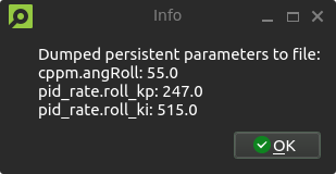
A new persistent parameter management area is introduced to the parameters tab of the client, with buttons for dumping, loading and clearing stored persistent parameters.An information dialog notifies users of the dumped persistent parameters and their values. Loading parameters will result in a similar pop-up.A confirmation dialog prevents accidental clearing of persistent parameters.
System-id code merged to master
Back in 2021, we created the system-id deck which we talked about in this blog post. It has not been officially released but a few users have gotten some PCBs and built it themselves. The functionality for the system-id deck has previously been in a branch, but as code in branches tends to become outdated, we have now moved this into the master branch utilizing the kbuild system instead. Building for the system-id deck is now as easy as doing “make sysid_defconfig” and then compiling. While talking about the system-id deck, let’s check the interest of releasing it as a product. It can help with system identification, tuning of controllers, improving efficiency etc. With enough interest there might be an economy in manufacturing it.
Out of stock
Unfortunately, we’re out of stock of Crazyflies at the moment. We expect some at the end of next week, so hopefully, you should be able to find them back in the store quickly.
Developer meeting
The next developer meeting will be on the 6th of March 2024, Arnaud will talk about the Crazyflie Client past, present and future, based on its last blog post. The client is still very useful but starts to show its age so we are looking at what should be kept, what should be improved and what should be removed. We will present what we have in mind, please come and discuss with us so we can shape the next 10 years of Crazyflie client!
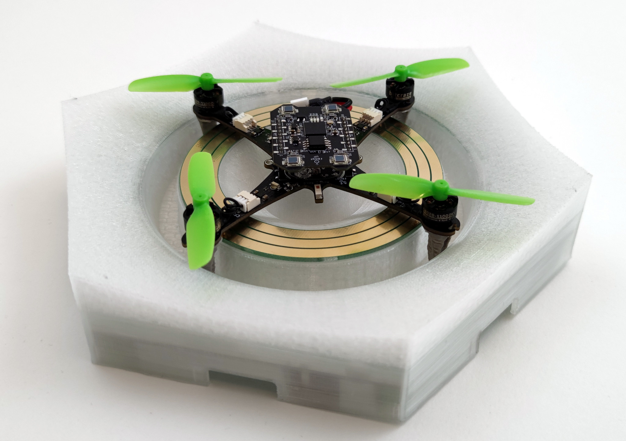
If you haven’t seen it yet then check out our latest Christmas video! In it, we show off a bunch of new stuff, with the main ones being the new Crazyflie brushless and the Lighthouse V2 (which supports up to 16 base stations). But there were also a few other things featured in the video! One of them is the charging pad the Crazyflie brushless takes off from and lands on in the video. This weeks blog post is about the charger, how it came to be, how it works and what lies ahead.
Some history
A while back I worked a bit on a contact charger for the Crazyflie 2.1. The idea was to try and make a design where small pogo-pins could be added to various decks which would allow the Crazyflie 2.1 to charge when lading on a charging pad. Some of the issues with the design was that the area was small (it had to fit on a deck), it put requirements on each deck and that some decks (like the Flow V2 deck) has components which are taller than the pogo-pins. So after the blog post back in 2021 this has been on the shelf, until recently when the Crazyflie brushless work has been moving forward.
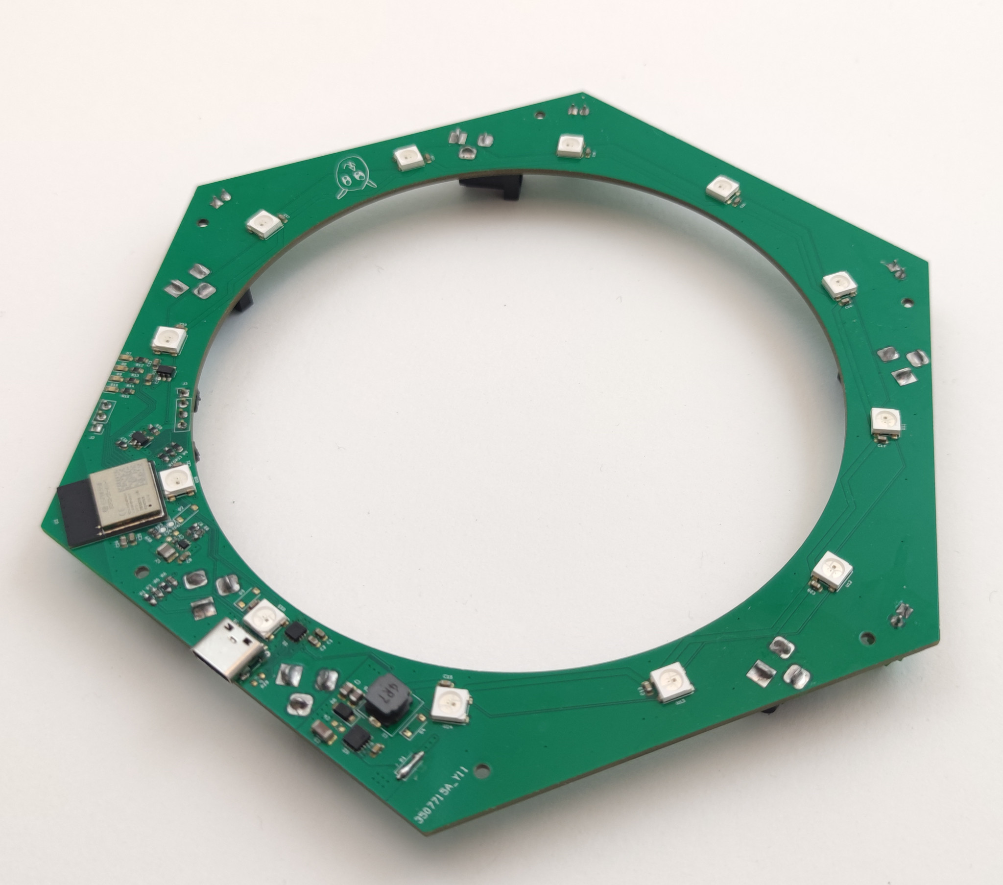
With the new prototype design for the Crazyflie brushless being made, there was a chance to address some of the issues I’ve seen before and do another try. All we needed was to add some pads for soldering pogo-pins on the wings (which actually wasn’t as easy as one would think due to layout constraints). So now the charging points didn’t have to be on each deck, they are built into the Crazyflie BL base. The distance between the points is also larger, allowing for a bigger hole in the charging PCB and allowing for a higher variety of decks, like the LED ring with the diffuser shown in the video.
The last missing part of the puzzle was when we needed to do more flight testing with the Crazyflie brushless. We wanted to reproduce the infinite flight demo we previously had for the Crazyflie 2.1, but the current Qi charger pad didn’t work with the new Crazyflie brushless. Time for the next iteration of the charger prototype!
Under the hood
So how complex can you make a charger? Lots! When making a prototype I like to add as much ideas possible to the design. Missing something you wanted to test and doing a new version takes a lot of time but adding some extra crazy ideas might be pretty quick in the design phase. A lot of the time ideas are scrapped along the way, most of the time because of space- or price constraints. Sometimes they are just bad or too complex. Luckily in this case the charger has a large PCB with lots of space and it’s just an early prototype so there’s (almost) no bad ideas!
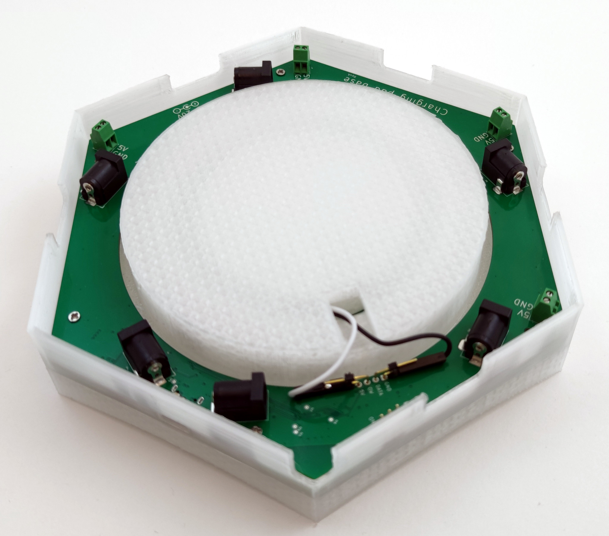
Under the hood (or 3D printed plastic in this case) there’s a bunch of stuff:
An WiFi/BLE module, the ESP32-C6-MINI
USB-C connector
USB-PD controller
6 DC-jack connectors and 5 terminals for connecting power
Measurement of charging current and supply voltage
12 WS2812B RGB LEDs for the outer ring and 12 for the inner one
20-to-5V DC/DC and 5-to-3V3 DC/DC
Some debugging LEDs and UART
Intended use
The idea with the contact charger has been to easily charge your Crazyflie without disconnecting the battery, plugging in the micro-USB connector or blocking the use of decks facing downwards like the Qi charger does. In addition to this I also wanted to try out some other ideas.
WiFi: For a long time I’ve had a prototype of a server for connecting various hardware to (like a charger) so I wanted to try to connect it to this for monitoring.
BLE: The idea was that the Crazyflie could talk to the charger via BLE to for instance change the light effect.
LEDs (and lots of them): The idea was to give some feedback from the charging of the Crazyflie but also to give the charger the ability to act as something more, like lighting up when a Crazyflie decides to land on it.
USB-PD: This is connected to the chaining of power. The ideas was to connect a USB-C charger and distribute the power from it to other chargers via the DC-jack.
Rust: Like we’ve written about before, we’ve been trying out more and more Rust here at Bitcraze. This is yet another experiment, the firmware for the charger is written in Rust using Embassy.
Future
Currently the charger is an internal project, since we use it in our lab for the infinite flight. But it’s of course something that would be exciting to offer our users if there any interest. So let us know what you think!
Also, don’t forget to join us for this Wednesday’s dev meeting. the main topic will be about the Kalman filters however we can answer questions about the wireless as well!
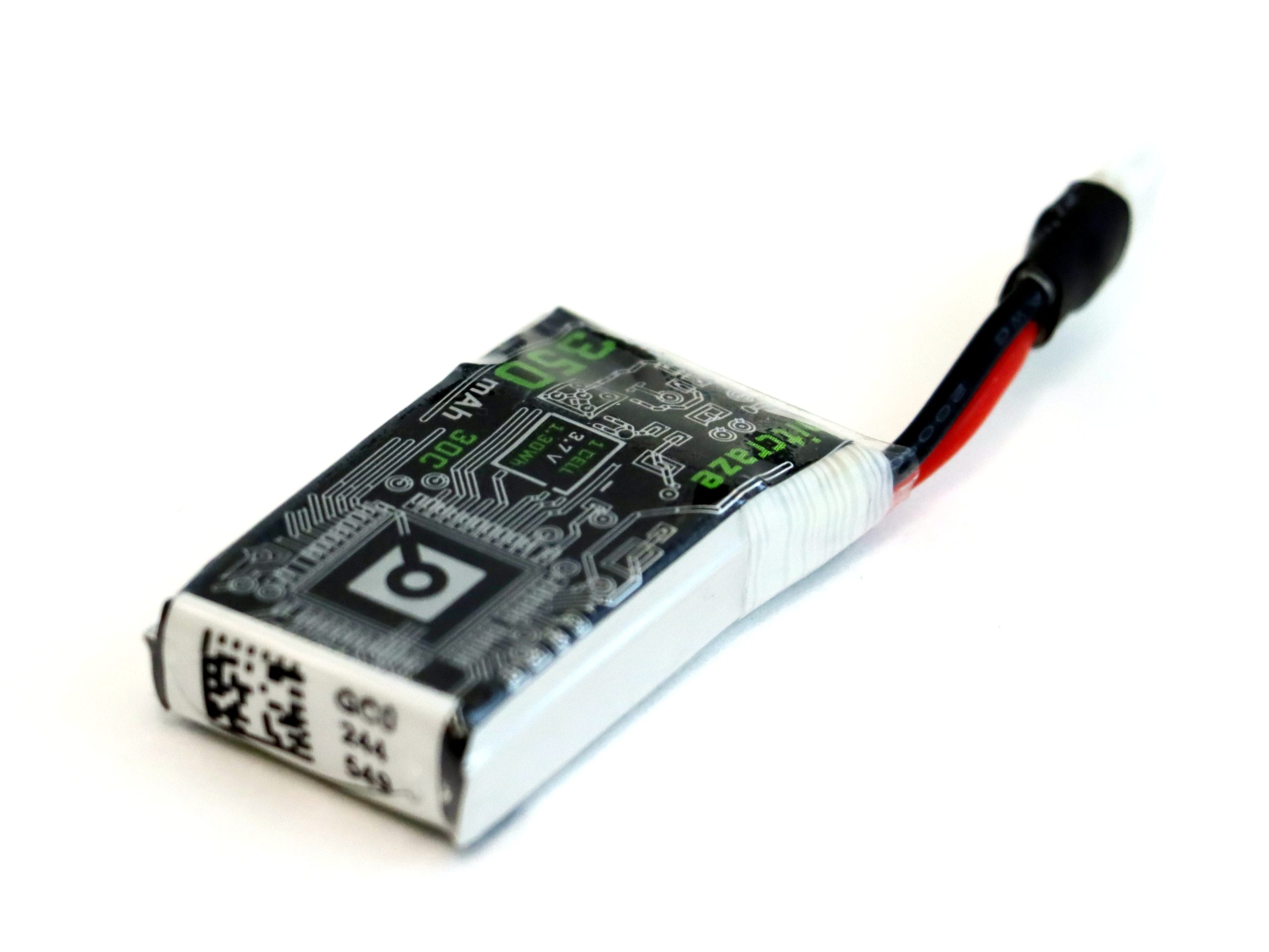
We are happy to announce that we are working on a new upgrade battery for the Crazyflies! It will soon hit production and hopefully, keeping our fingers crossed, it will arrive in our stock in early 2023-Q4.
The upgrade battery is based on the “Tattu 350mAh 3.7V 30C 1S1P” cell and with some additional great features:
Protection Circuit Module (PCM) to protect against short circuits, overcharge, over discharge etc.
Gold-plated connectors for lower contact resistance.
Shrink wrap around connector for better rigidity.
Cool Bitcraze matched graphics.
And if we list the benefits compared to the stock Crazyflie battery:
Higher current capabilities, 30C burst current, that is >10 Amp.
350mAh instead of 250mAh
Higher energy density, ~130 Wh/kg instead of ~105 Wh/kg
There are some drawbacks too:
It is ~1 mm thicker and does not fit well with all deck boards and the short or medium size pin headers. We will release longer pin headers at the same time though.
Price will be higher
~1.5 grams extra weight
With this upgrade battery, you will experience longer flight times, more “punch” during acceleration and it is great combined with the thrust upgrade kit!
As some of you may know, I’ve worked at Bitcraze for two summers (2019, 2020), and I did my Bachelor’s thesis here during the spring this year. While we mentioned shortly that I started working on my thesis (here), I never presented the results of it, so I thought that I’d do that now! Better late than never, right?
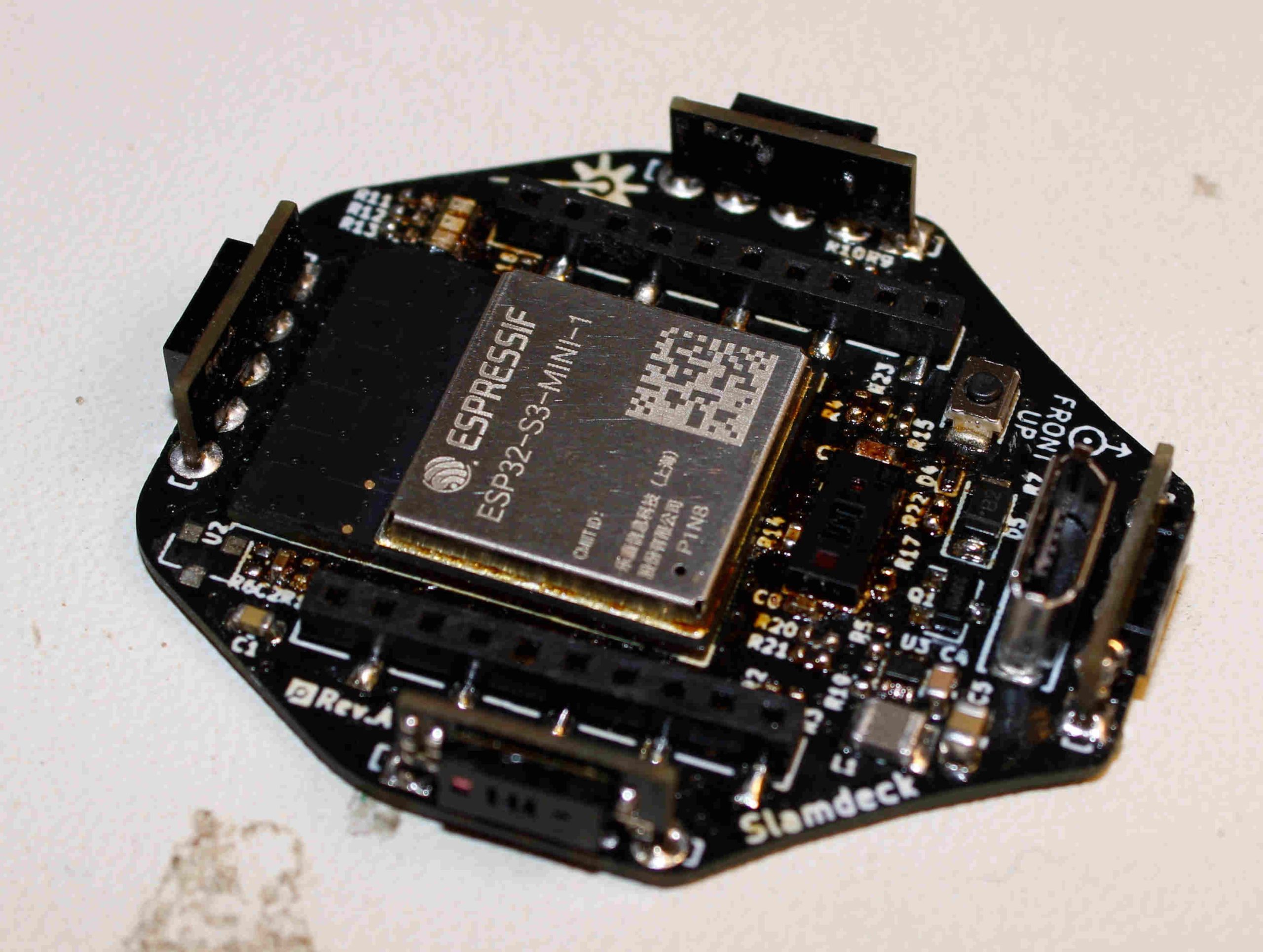
So, during my thesis I built a prototype deck for the Crazyflie which contained five multizone lidar sensors (VL53L5CX) and an ESP32-S3. The VL53L5CX sensors can output distances to a 8×8 grid, with a 45 degrees FoV at a rate of 15 hz. The purpose of the ESP32-S3 was to collect the data from the sensors and send it to a ground control station, either with WiFi, or, with the nRF radio on the Crazyflie. While the ESP32-S3 is quite overkill for only collecting data and send it, we weren’t sure of how much data that would be gathered from the sensors, so to be on the safe side we rolled with the ESP32-S3. Both the sensors and the microcontroller was very new at the time so it seemed like a good oportunity to try them out.
I designed the schematic in KiCad and got a lot of help from everyone here at Bitcraze while doing so, especially Tobias. Once the schematic was done I designed the PCB, ordered the components and then waited eagerly for the stuff to arrive. Once everything had arrived, I soldered all components and assembled the deck. I then wrote some firmware for the ESP32-S3, and the STM32 on the Crazyflie, and at last I wrote a simple GUI in PyQt to help visualize the data, both in 2D and 3D.
The deck was quite successful and while the GUI was very far from perfect, I think it did show that the deck has some nice potential and it was very cool to see the 3D point cloud in realtime while flying the Crazyflie! I tried sending the data over WiFi which worked perfectly well, and I also tried sending it through the nRF on the Crazyflie with the help of CPX, which also worked pretty well.
If you’re more curious about the thesis, feel free to check it out here, and the github repository can be found here.
I finished the thesis in the beginning of the summer, and I have been working part time here at Bitcraze since September and I’ve truly been loving! I think it’s been really cool to become a part of the team and work more on the regular stuff that the rest of the team does. It has been very interesting to see how the team works and cooperates on a daily basis. Something that striked me was just how many products and different features and services we handle here, with only six people!
Fortunately and unfortunately, I will be moving to Gothenburg next week which means that my time at Bitcraze is over, for this time. I have learned a lot from everyone here and truly appreciate all the love and support, which actually started before I even started my Bachelor’s degree.
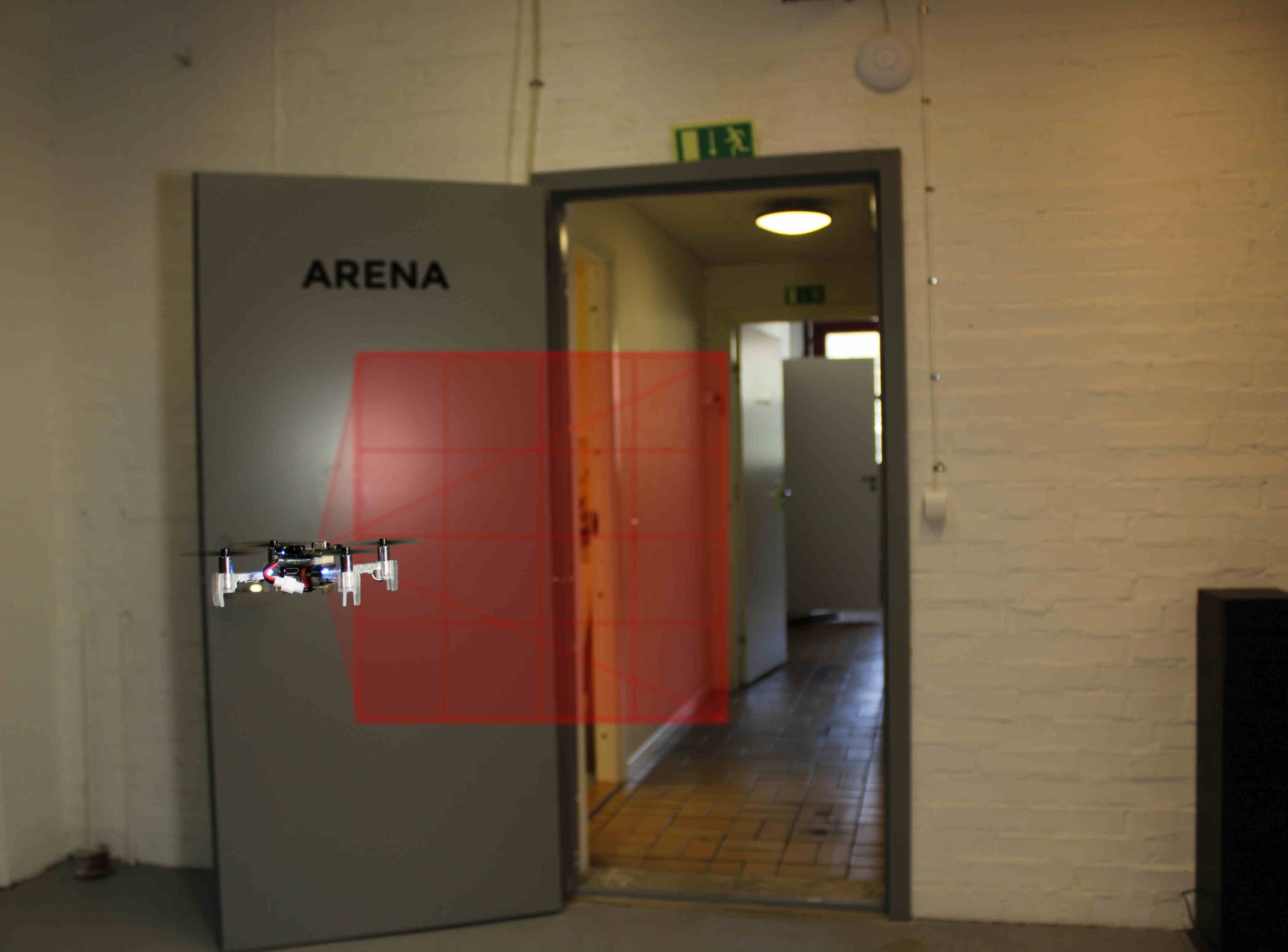
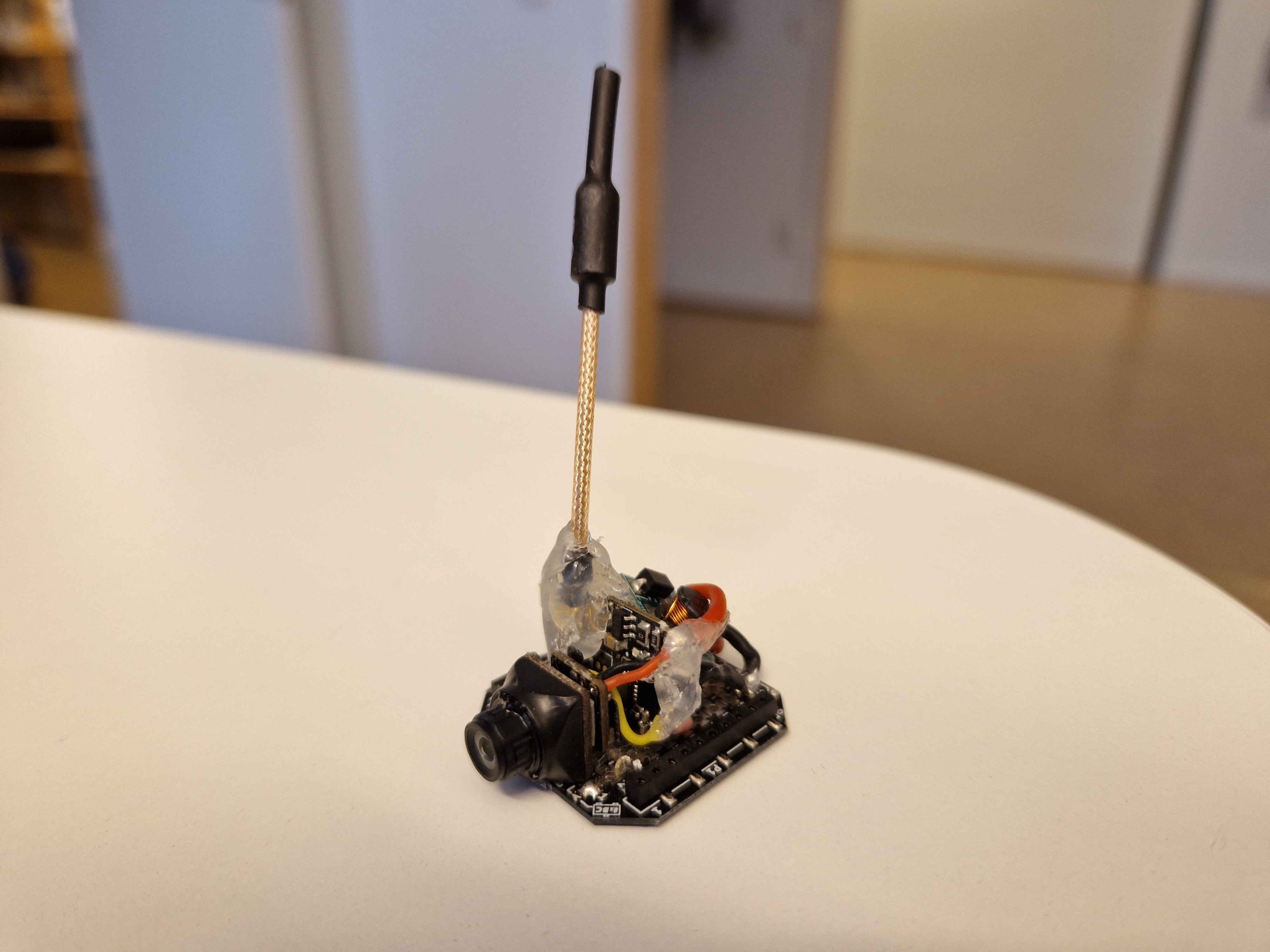
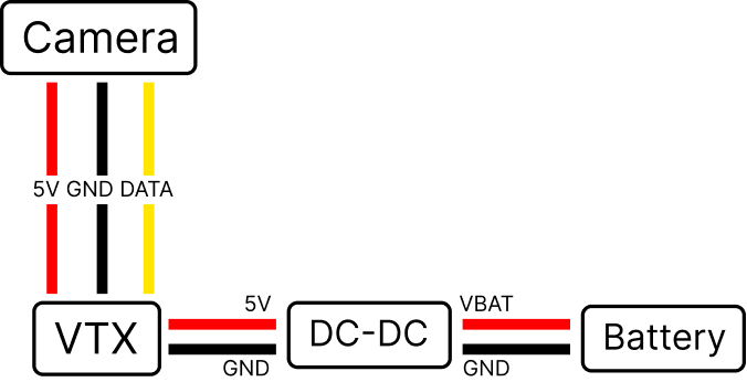
I’ve been flying FPV drones for some time and while I usually fly bigger drones (3-5 inch props) I have always wanted to put an analog camera on the Crazyflie to fly it in FPV. So, a few weeks ago I put together a simple FPV deck using off-the shelf components! The deck simply consists of a camera, VTX and a DC-DC converter, soldered onto a prototype deck.
The deck is very simple and consists of only four components and the price (as of writing) is approximately 50$ in total.
I soldered the components onto the prototype deck and used some hot glue to attach the camera, as well as on and around the antenna to prevent it from breaking off when crashing. The deck weighs a total of 8.5 grams including connection pins.
I used the newly released upgrade kit on the Crazyflie which made it easier to fly since the motors and propellers makes the drone a lot faster and easier to control flying manually. The upgrade kit also increases the lift capacity of the drone, which is nice so that the extra weight of the camera deck doesn’t become a problem.
Radio Controller
When flying FPV race drones you typically want a nice radio controller and there are many options to choose from. I recently got myself a RadioMaster Zorro Radio Controller – 4-in-1 Multi-Protocol which supports a whole variety of different RC protocols, including the popular ones such as frsky, flysky and many more. You can run the popular OpenTX or EdgeTX firmware on it and the controller is equipped with multiple RF chips, whereas one of the chips is the nRF24L01. This means that we can control the Crazyflie with the controller! While I expected several hacks to make this work, thanks to the awesome Bitcraze community someone had already written support for the Crazyflie for the controller.
Below are the steps that I took to control the Crazyflie using a RadioMaster Zorro 4-in-1 controller. In short, we want two different firmwares: 1) Firmware for the remote controller (like the controller OS). 2) Firmware for the internal RF module. Please note that the details of the steps might change in the future, but hopefully it can still be helpful.
Locate the file Multiprotocol/CFlie_nrf24l01.ino in the repository and set the address of the Crazyflie that you want to connect to in the method CFLIE_initialize_rx_tx_addr().
Ensure that the #define CFLIE_NRF24L01_INO is uncommented in the file Multiprotocol/_Config.h
Download Arduino IDE in order to build the code for the internal RF module.
Open Arduino IDE from the Multiprotocol directory and build the code by Sketch -> Export Compiled Binary. This might take some time since the firmware is quite big. The binary can then be found in Multiprotocol/build/XXX.bin.
Plug in the SD card of the remote controller or connect it to the computer using USB-C and start the controller as a storage device.
Transfer the two firmware binaries to the firmware directory of the radio controller. Unplug the radio controller and install the EdgeTX/OpenTX binary as the radio firmware, and the Multiprotocol binary for the internal RF module.
Create a new model and select the CFLIE protocol.
You should now be ready to fly! So turn on your Crazyflie and ensure that it’s on the address that you assigned in the CFLIE_initialize_rx_tx_addr() method in step 3. The radio should automatically find the correct channel so you shouldn’t have to worry about selecting the right channel.
Conclusions
I think the deck turned out really nice and it’s super cool to fly the Crazyflie in FPV! :) Some notes to consider:
It’s possible to fly with the FPV deck with the normal motors and propellers of the Crazyflie but with the thrust upgrade kit the flying is easier and significantly more enjoyable since you can go a lot faster.
Ensure that the battery is well and fully charged before flying.
There’s no support for On-Screen Display (OSD) on this deck, but it would be a cool thing to test in the future. I believe that most flight controllers that supports onboard OSD has the MAX7456 or AT7456E chip, but there’s probably more ways to do it.
The hot glue loosens up slightly from the heat dissipation of the VTX. I added some extra glue and it seems to hold quite well, even after multiple crashes.
There are modules that contains the camera and the VTX in the same package, which might be a good/better option for the Crazyflie buying them separately and soldering them together.
Please let me know if you’ve found any mistakes in the text above or if you have any other cool ideas or hacks about FPV for the Crazyflie! :)
The communication protocols between a PC, a Crazyradio and a Crazyflie are critical parts of the Crazyflie ecosystem, they allow to communicate with and control the Crazyflies in real time. These protocols have been documented in a couple of blog posts already. They exist since the origin of the Crazyflie, in 2011, and where originally designed with one use-case in mind: controlling one Crazyflie manually from a game-pad connected to a PC. The Crazyflie can of course do much more nowadays, like flying in big autonomous swarm, but the underlying communication protocols are still an evolution of these simple manual-flights single Crazyflie origin.
Over time we have felt the limitations of the communications protocols and of the Crazyradio (PA). For this reason, lately, we have been starting to work at making a new, more modern, Crazyradio dongle and at revamping the communication protocol used to communicate with the Crazyflie. The aim is to start with the current Crazyflie use-cases including flying in centralized and decentralized swarms with varying levels of autonomy of the drone itself.
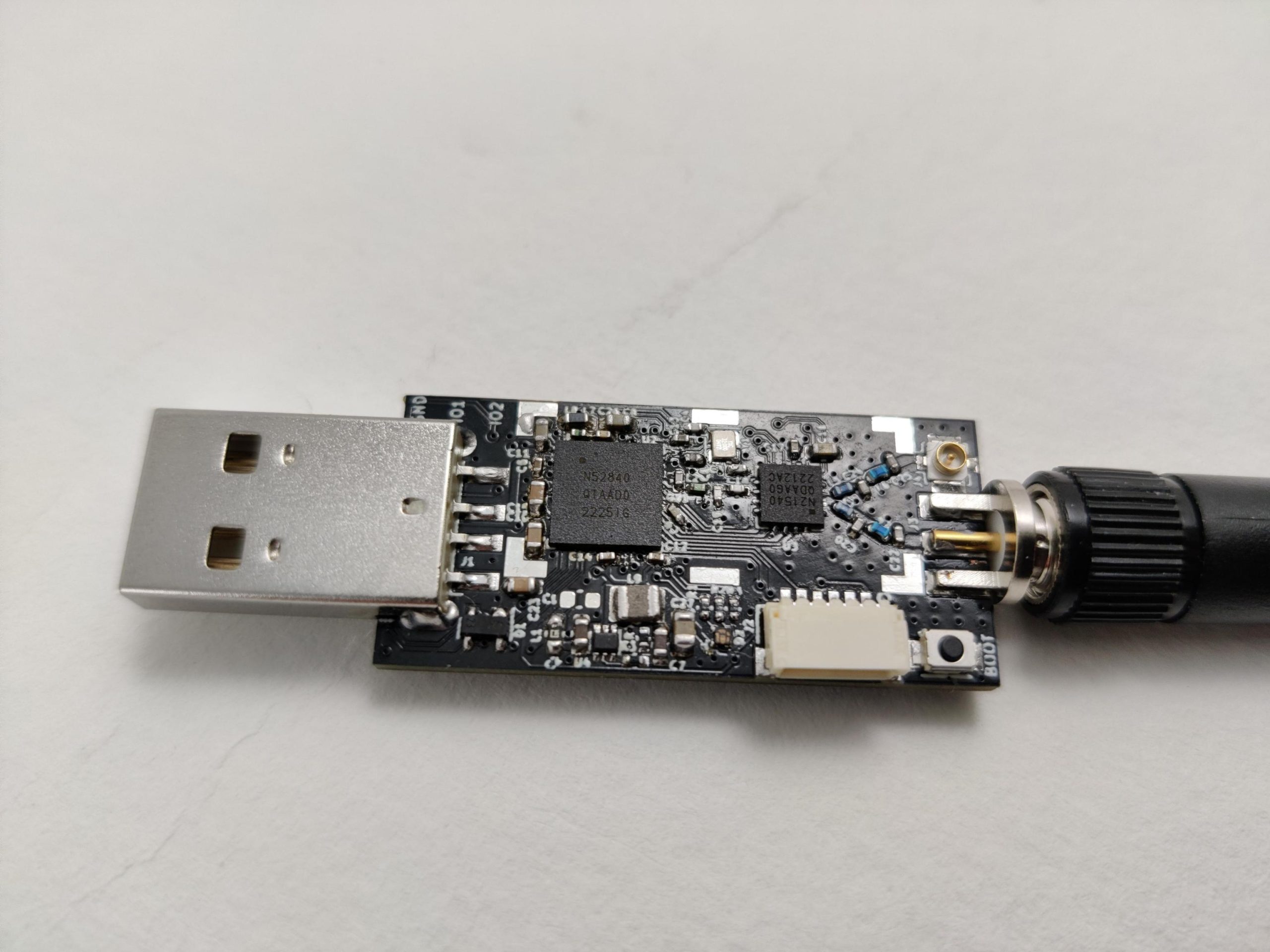
The first project is to make a new Crazyradio dongle: the current Crazyradio PA is based on an old nRF24 chip from Nordic semi. It runs on a 8051 microcontroller and has a mostly hardware-driven radio. This means that the processing power is quite limited and the radio has no flexibility with the on-air protocol and packet size limited to 32 Bytes. We are working on a new Crazyradio dongle based on an nRF52840 microcontroller and a RF power amplifier. We expect the new radio to be available sometimes before the summer 2023:
The main advantage of using the new nRF52 microcontroller is that it is an ARM Cortex-M4 chip with quite a lot of flash and ram. This will make development much easier and faster. It is also a much more capable chip which will improve communication performance. The output power will be similar to the Crazyradio PA so the range should be similar. The radio being more flexible, it will allow development of new protocols including the capability to send packets bigger than 32 bytes.
On the USB protocol side, we will take this opportunity to improve the USB protocol. We are making it more flexible so that it can be expanded more easily in the future and it will also be much more efficient when controlling swarm of Crazyflies.
The first version of the new Crazyradio will implement the same air-protocol as the current one, so there will not be a need to change the Crazyflie firmware right away.
However we are already thinking of a couple of new radio protocol that we want to develop for the new Crazyradio and the Crazyflie 2:
A low latency channel hopping protocol: This protocol would allow to connect one or a swarm of Crazyflie using channel hopping. This means that the user does not have to setup a channel for communication anymore, the protocol will automatically hop form channel to channel randomly. This will make it much easier to connect to Crazyflies and make the link more reliable
A P2P protocol that will allow Crazyflies and Crazyradios to talk to each other: the main idea is to make the P2P protocol a proper supported protocol and to make the Crazyradio able to be a node in the P2P network. This should simplify a lot the development of autonomous swarm.
On the higher level protocol, CRTP, we are stating to think of ways to make new protocols as well. On that side, there has been no work started yet but a lot of ideas and general direction based on our experience and on feedback in iROS 2022 and other conferences. The basic lose ideas currently are:
Integrating the concept of connection in the protocol: currently there is no such concept so for example if a logging is setup and the link is lost, the logging subsystem will continue to try to send packets forever. A more logical implementation would tell the logging subsystem that the connection is lost and so that the logging can be canceled.
Basing the protocol on Remote Procedure Call: A lot of that we currently do in CRTP is to emulate procedure call with packets and parameters. Making procedure call the base unit of the protocol would make it much easier to use and extend
Versioning! One of the problem currently is that without clear versioning, it is very hard to make the protocol evolve in a documented way. We will find a way to version so that we can improve, add and remove functionality when needed.
Finally. We are not planning on running (micro) ROS in the Crazyflie 2, however the goal is to make a protocol that would make the interface to (micro) ROS and Crazyswarm as thin and boring as possible. Today the Crazyswarm ROS Crazyflie server is a full fledged client, the hope is to make the Crazyflie protocol in such a way that it would look more like a proxy to the Crazyflie RPC API.
If you have made a client that communicates directly with the Crazyradio PA, the change in the new Crazyradio will affect you. We will soon make the new Crazyradio 2 repos public with documentation of the new protocol to give the possibility to have discussions before release.
Those are still very lose ideas and the main goal of this blog post is to bring awareness to the future work: if you have any ideas, opinion or wishes when it comes to the communication protocol please come in contact with us and let’s discuss. The best forum is our github discussion page. Also we are planning to have an online townhall meeting so that we can handle any questions about implementation or discuss the proposed protocol, so keep an eye on this discussion thread: Townhall meeting (7 Dec 2022) · Discussion #426 · bitcraze (github.com).
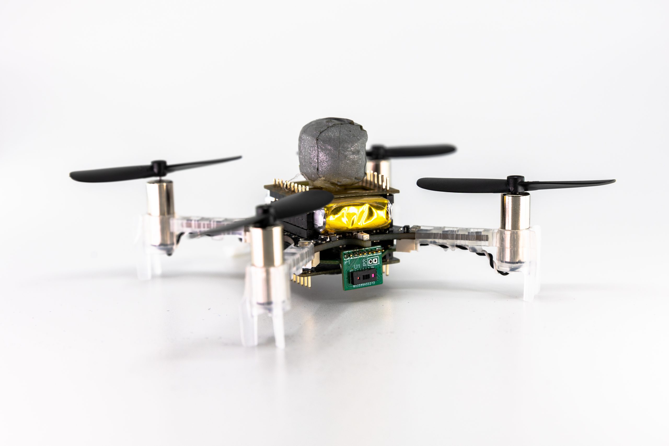
This weeks guest blog post is from Hanna Müller, Vlad Niculescu and Tommaso Polonelli, who are working with Luca Benini at the Integrated Systems Lab and Michele Magno at the Center for Project-Based Learning, both at ETH Zürich. Enjoy!
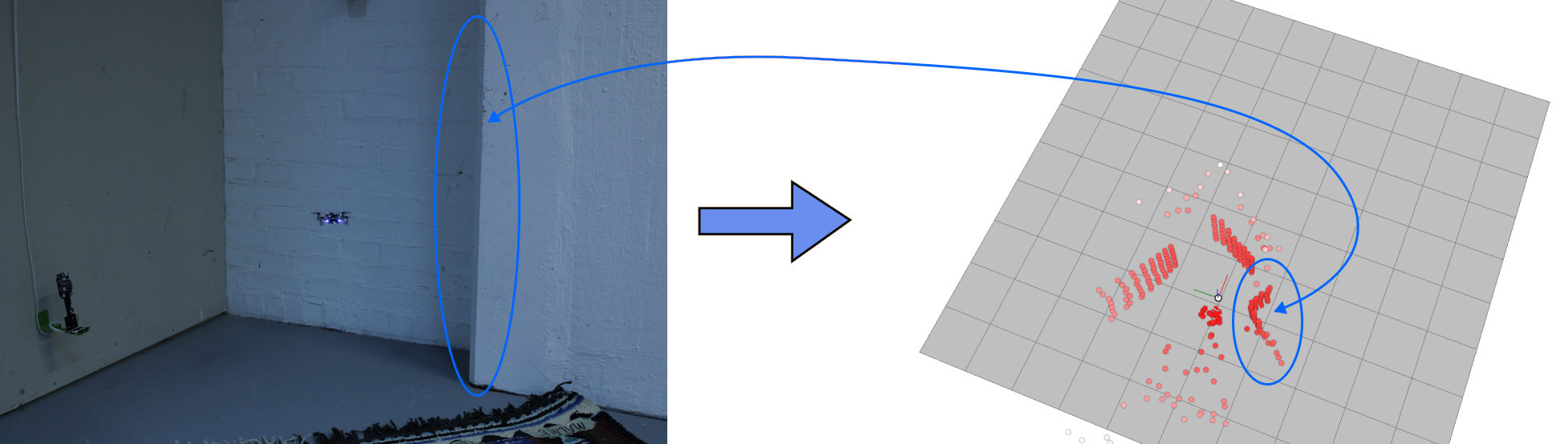
This blog post will give you some insight into our current work towards autonomous flight on nano-drones using a miniaturized multi-zone depth sensor. Here we will mainly talk about obstacle avoidance, as it is our first building block towards fully autonomous navigation. Who knows, maybe in the future, we will have the honor to write another blog post about localization and mapping ;)
A Crazyflie 2.1 with our custom multi-zone ToF deck, a flow deck and a vicon marker.
Obstacle avoidance on nano-drones is challenging, as the restricted payload limits on-board sensors and computational power. Most approaches, therefore, use lightweight and ultra-low-power monocular cameras (as the AI-deck) or 1d depth sensors (as the multi-ranger deck). However, both those approaches have drawbacks – the camera images need extensive processing, usually even neural networks to detect obstacles. Neural networks additionally need training data and are prone to fail in completely new scenarios. The 1d depth sensors can reliably detect obstacles in their field of view (FoV); however, no information about the size or exact position of the obstacle is obtained.
On bigger drones, usually lidars or radars are used, but unfortunately, due to the limited weight and power consumption, those cannot be carried and used on nano-drones. However, in 2021 STMicroelectronics introduced a new multi-zone Time-of-Flight (ToF) sensor – with maximal 8×8 pixel resolution, a range up to 4m (according to the datasheet), a small form-factor and low power consumption of only 286mW (typical) it is ideal to use on nano-drones.
In the picture on top, you can see the Crazyflie 2.1 with our custom ToF deck (open-sourced at https://github.com/ETH-PBL/Matrix_ToF_Drones). We described this deck for the first time in [1], together with a sensor characterization. From this, we saw that we could use the sensor in different light conditions and on different colored obstacles, but from 2m on, the measurements started to get incomplete in all scenarios. However, as the sensor can detect invalid measurements (due to interference or obstacles being out of range), we can still rely on our information. In [2], we presented the system and some steps towards obstacle avoidance in a demo abstract, as you can see in the video below:
The next thing we did was to collect a dataset – we flew with different combinations of decks (flow-deck v2, AI-deck, our custom multi-zone ToF deck) and sometimes even tracked by a vicon system. Those recordings amount to an extensive dataset with depth images, RGB images, internal state estimation and the position and attitude ground truth.
We then fed the recorded data into a python simulation to develop an obstacle avoidance algorithm. We focused on only the ToF data (we are not fusing with the camera in this project, we just provide the data for future work). We aimed for a very efficient solution – because we want it to run on-board, on the STM32F405, with low latency and without occupying too many resources. Our algorithm is very lightweight but highly effective – we divide the FoV in different zones, according to how dangerous obstacles in those areas are and then use a decision tree to decide on a steering angle and velocity.
With only using up 0.31% of the computational power and 210 μs latency, we reached our goal of developing an efficient obstacle avoidance algorithm. Our system is also low-power, the power to lift the additional sensor with all accompanying electronics as well as the supply of it totals in less than 10% of the whole drone. On average, our system reaches a flight time of around 7 minutes. We refer to our preprint [3] for details on our various tests – they include flights with distances up to 212 m and 100% reliability and high agility at a low speed in an office environment.
As our paper is currently submitted but not yet accepted our code and dataset are not yet released – however, the hardware design is already accessible: https://github.com/ETH-PBL/Matrix_ToF_Drones
[1] V. Niculescu, H. Müller, I. Ostovar, T. Polonelli, M. Magno and L. Benini, “Towards a Multi-Pixel Time-of-Flight Indoor Navigation System for Nano-Drone Applications,” 2022 IEEE International Instrumentation and Measurement Technology Conference (I2MTC), 2022, pp. 1-6, doi: 10.1109/I2MTC48687.2022.9806701. [2] I. Ostovar, V. Niculescu, H. Müller, T. Polonelli, M. Magno and L. Benini, “Demo Abstract: Towards Reliable Obstacle Avoidance for Nano-UAVs,” 2022 21st ACM/IEEE International Conference on Information Processing in Sensor Networks (IPSN), 2022, pp. 501-502, doi: 10.1109/IPSN54338.2022.00051. [3] H.Müller, V. Niculescu, T. Polonelli, M. Magno and L. Benini “Robust and Efficient Depth-based Obstacle Avoidance for Autonomous Miniaturized UAVs”, submitted to IEEE, preprint: https://arxiv.org/abs/2208.12624
After a period of bitcrazer-vacations, we are now all back at work. The summer here in Sweden has generally been great. Some of us stayed here to keep the company afloat, and some just stayed afloat on lakes or the sea. The majority vacationed inside of Sweden, but some (could you guess who?) have visited France, Italy, or Greece. We’ve been lucky with a mostly warm and sunny weather, perfect for bathing and grilling. And even though it’s nice to enjoy real summer, it’s still worrying sign though, as Europe is experiencing what could be the worst drought in 500 years.
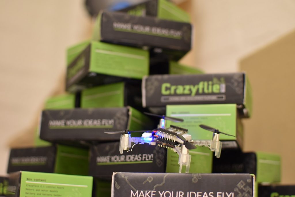
Crazyflie 2.1 back in stock
What is also back is the Crazyflie 2.1, but back in stock, yay! After almost two weeks without any drones available for sale, we received a new batch of our quadcopter today. It should now be available in the shop, just in time for when school starts!
We got some indications the component shortage are slowly moving in the right direction so hopefully it will get easier to keep things in stock in the future. We are keeping our fingers crossed.
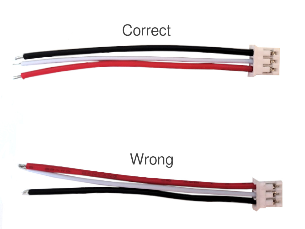
Bolt 1.1 ESC cable red/black switched
Unfortunately we recently found out that there has been a manufacturing error with the ESC cables that come with the Bolt 1.1. The black and red cables have been switched. Please see the image below.
With the black and red cables switched this will result in powering your ESCs with reversed polarity. This will most likely burn the MOSFET on the Bolt that controls the power to the ESC, which is the weakest link. This because the MOSFET body diodes on the ESC will conduct and make the whole ESC a short circuit. In many setups, e.g using 4in1 ESC these cables are not used though and will not cause a problem.
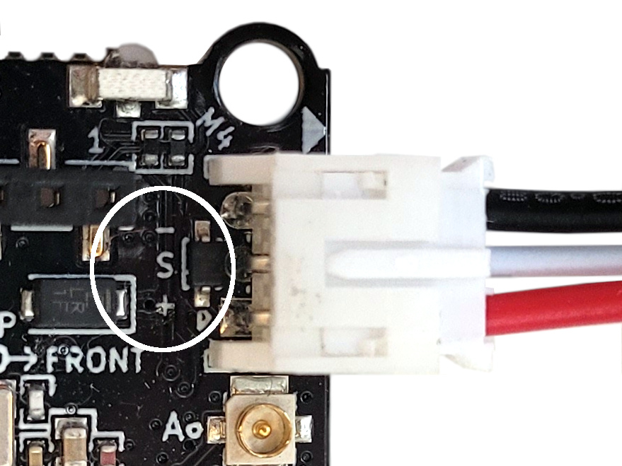
Switching the cables back is quite easy to do. Use a needle, tweezer or e.g. small screwdriver to open the plastic lock so the cable can be pulled out. Switch the black and red and you are done. You can double check that the colors are correct by comparing it with the Bolt 1.1 board. The plus and minus should match with the red and black as per the image below:
We are currently working with the manufacturer to get correct cables. If you got a Bolt 1.1 (anytime between June and August 2022) we can of course ship you correct cables once they are ready or give you support if you got problems with the control board. If so, please send us an email to support@bitcraze.io. Sorry for this inconvenience!
Unmanned Aerial Vehicles (UAVs) have garnered much attention from both researchers and engineers in recent decades. Aerial robots in general are classified into mainly three categories: fixed wings, rotary wings and flapping wings.
Fixed wings are one of the most common aerial vehicles as it has relatively higher power efficiency and payload capacity than other types, thanks to their big and highly customizable wing. But this also leads to a bigger footprint and usually the lack of ability for Vertical Taking Off and Landing (VTOL). Rotary wings generally include helicopter and multirotors (such as quadrotors), and they have recently become increasingly popular in our daily lives. Easily achieving great performance in attitude and position control, rotary wings are widely applied in many fields. Flapping wing robots take inspirations from small flapping insects (such as Harvard Robobee) or birds (Purdue Hummingbird Robot).
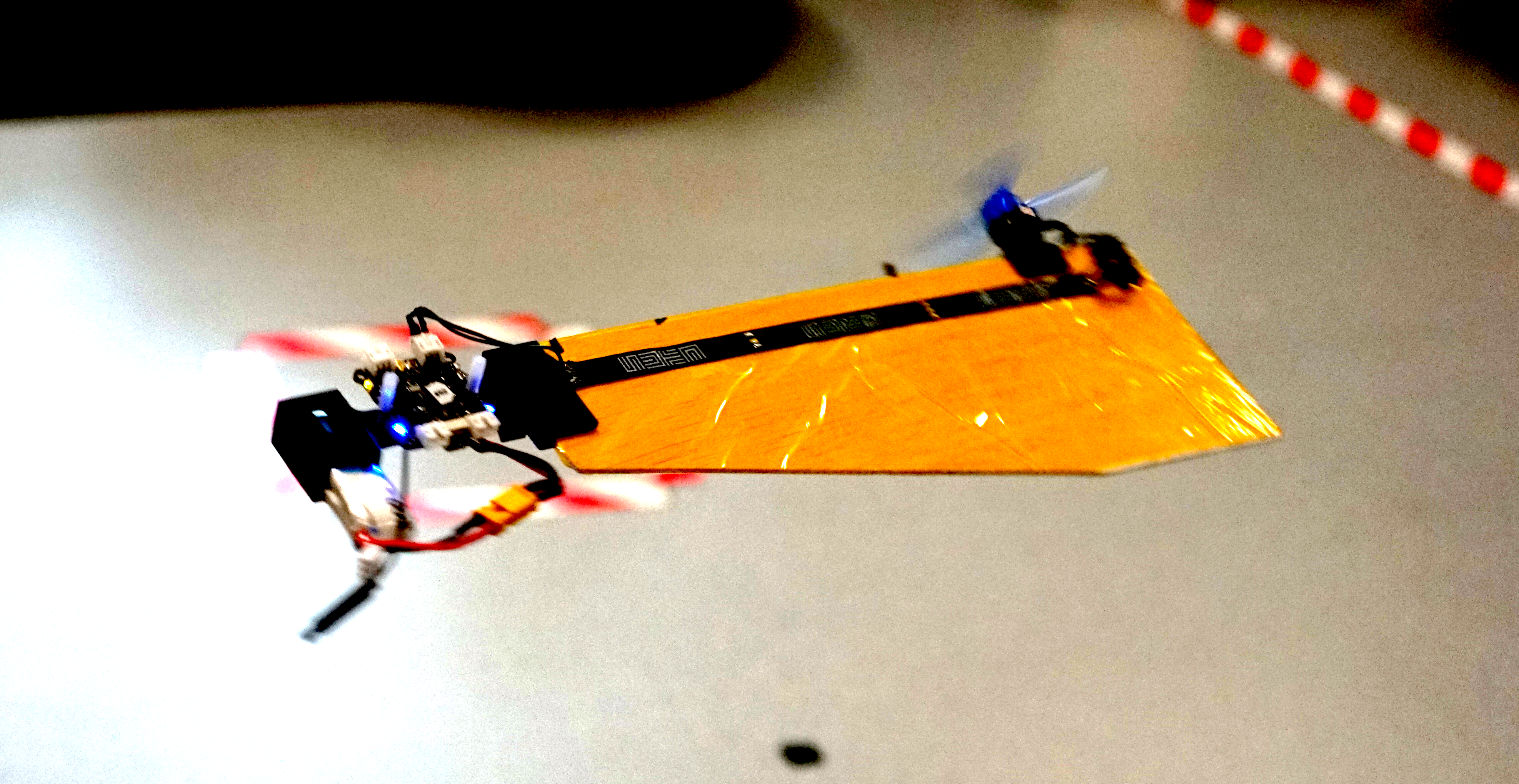
Fig: A simple prototype of SAM from SUTD with Crazyflie Bolt.
Monocopters are largely inspired from the falling motion of maple seeds, and they are relatively much simpler to build as compared to its counterparts. They can keep a relative smaller footprint and achieve decent control performance although they are highly underactuated. The Single Actuator Monocopter (SAM) has the ability to VTOL, perform 3D trajectory tracking as well as maintain high hovering efficiency. With those advantages, rapid developments have been made in recent years such as the Foldable Single Actuator Monocopter (F-SAM) and Modular Single Actuator Monocopter (M-SAM) from Engineering Product Development (EPD) of Singapore University of Technology and Design (SUTD).
Taking inspiration from nature – Samara inspired monocopter
A descending samara or maple seed, is able to passively enter auto-rotation motion and stabilize its flight attitude, helping to slow down its descent speed and travel further for better survival of the species. This natural behavior attracts interests from scientists and researchers. With previous studies, we learnt that this passive attitude stability is mainly guaranteed by mass distribution (Center of Mass) and wing geometry (Center of Pressure) as well as the rotation motion.
A maple seed inspired Single Actuator Monocopter (SAM).
The SAM is designed to be very close in its mechanical make-up to its natural sibling, having a large single wing structure and a smaller, denser ‘seed’ structure. A single motor with propeller is installed on the leading edge, parallel to the wing surface. Comparing with flight dynamics of the original maple seed, SAM has extra torques and force caused by the spinning propeller, including a reaction torque and thrust directly from propeller, as well as an extra torque caused by precession motion. As a result, the balance of the combined forces and torques allows SAM to enter a new equilibrium condition while still retaining the passive attitude stability.
Development of monocopters
The research on monocopters can be traced back to a long time ago. Here are some examples of different types of air frame to roughly introduce their developments. An air-frame called Robotic Samara [1] was created in 2010, which has a motor to provide rotational force, a servo to control collective pitch of the wing, a winged body fabricated by carbon fiber, and a lipo battery. In the following year, Samarai MAV [2] was developed by following the mass distribution of a natural maple seed. To achieve the control, a servo is equipped to regulate the wing flap. In 2020, a single actuator monocopter was introduced with a simplified air-frame [3]. The main structure is made by laminated balsa wood while the trailing edge of the wing is made by foam for better mass distribution. By making use of the passive attitude stability, only one actuator is required to control the position in 3D space. Based on which, F-SAM [4] and M-SAM [5] were developed in 2021 and 2022 respectively.
SAM with foldable wing structure (F-SAM).
A Modular SAM (M-SAM) with Crazyflie Bolt
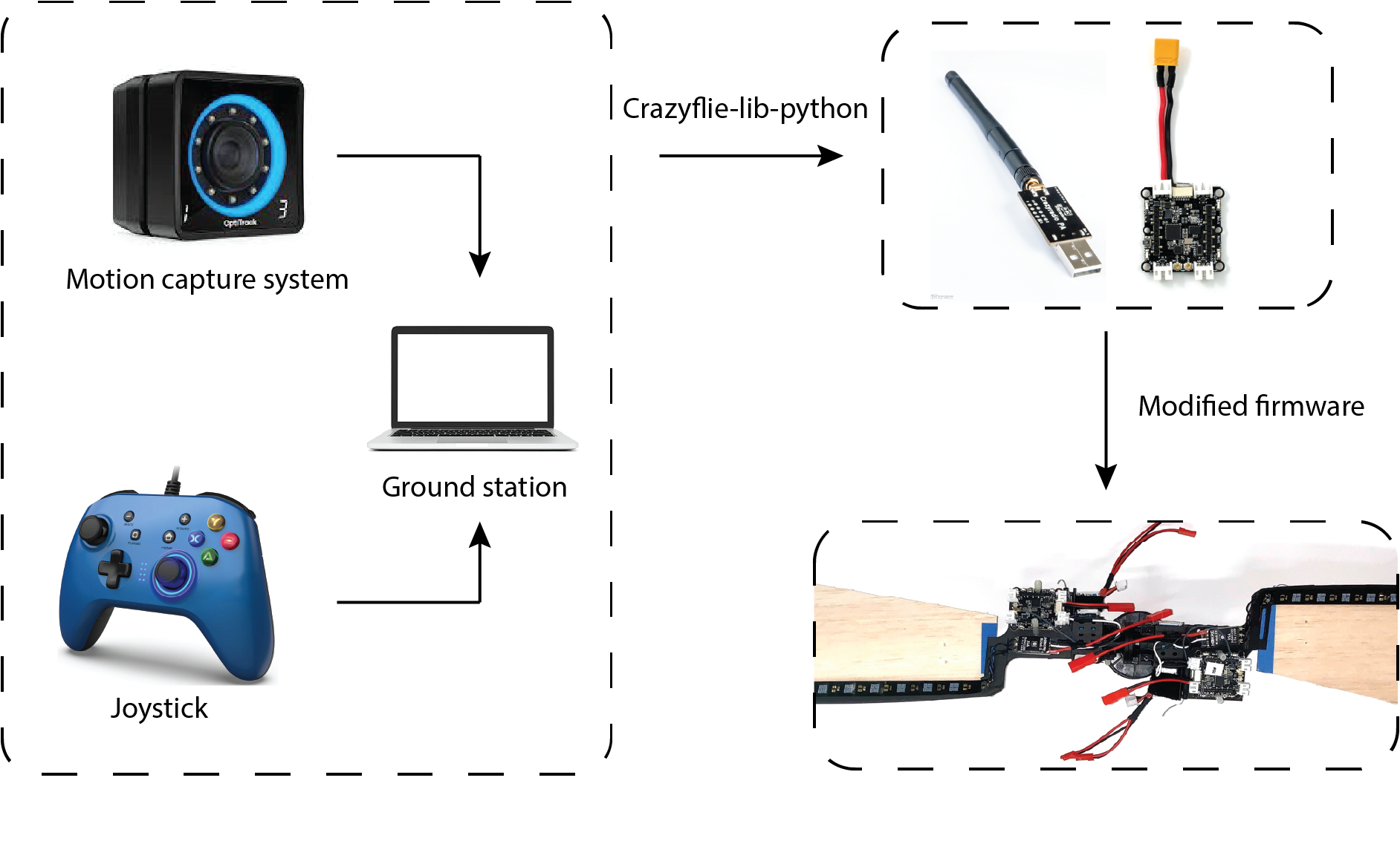
Thanks to its easy implementation and reliable performance, we use the Crazyflie Bolt as the flight controller for M-SAM. Like other robotic systems, the ground station is integrated with motion capture system (position and attitude feedback for both control and ground truth) and a joystick (control reference directly generated by user) is responsible for sending filtered state feedbacks and control references or control signal directly to flight controller. This is realized by employing the Crazyradio PA under the Crazyflie-lib-python environment. Simple modifications from the original firmware were made to map from the control reference to motor command (a customized flight controller).
A diagram shows how Crazyflie Bolts work in M-SAM project.
Another advantage of using Crazyflie Bolt in M-SAM project is its open source swarm library. Under the swarm environment, SAMs can fly in both singular and cooperative configurations. With simple human assistance, two SAMs can be assembled into cooperative configuration by making use of a pair of magnetic connectors. The mid-air separation from cooperative configuration to singular configuration is passively triggered by increasing the rotating speed until the centrifugal force overcomes the magnetic force.
Modular Single Actuator Monocopters (M-SAM), which is able to fly in both singular and cooperative configuration.
Potential applications
What kinds of applications can be achieved with the monocopter aerial robotic platform? On the one hand, many applications are limited by the nature of self-rotation motion. On the other hand, the passive rotating body also offers advantages in some special scenarios. For example, SAM is an ideal platform for LIDAR application, which usually requires the rotating motion to sense the environment around. Besides, thanks to simple mechanical design and cheap manufacturing cost, SAM can be designed for one time use such as light weight air deployment or unknown, dangerous environments.
An example [6] shows the potential applications of a rotating robot with camera.
Reference
[1] Ulrich, Evan R., Darryll J. Pines, and J. Sean Humbert. “From falling to flying: the path to powered flight of a robotic samara nano air vehicle.” Bioinspiration & biomimetics 5, no. 4 (2010): 045009.
[2] Fregene, Kingsley, David Sharp, Cortney Bolden, Jennifer King, Craig Stoneking, and Steve Jameson. “Autonomous guidance and control of a biomimetic single-wing MAV.” In AUVSI Unmanned Systems Conference, pp. 1-12. Arlington, VA: Assoc. for Unmanned Vehicle Systems International, 2011.
[3] Win, Luke Soe Thura, Shane Kyi Hla Win, Danial Sufiyan, Gim Song Soh, and Shaohui Foong. “Achieving efficient controlled flight with a single actuator.” In 2020 IEEE/ASME International Conference on Advanced Intelligent Mechatronics (AIM), pp. 1625-1631. IEEE, 2020.
[4] Win, Shane Kyi Hla, Luke Soe Thura Win, Danial Sufiyan, and Shaohui Foong. “Design and control of the first foldable single-actuator rotary wing micro aerial vehicle.” Bioinspiration & Biomimetics 16, no. 6 (2021): 066019.
[5] X. Cai, S. K. H. Win, L. S. T. Win, D. Sufiyan and S. Foong, “Cooperative Modular Single Actuator Monocopters Capable of Controlled Passive Separation,” 2022 International Conference on Robotics and Automation (ICRA), 2022, pp. 1989-1995, doi: 10.1109/ICRA46639.2022.9812182.
[6] Bai, Songnan, Qingning He, and Pakpong Chirarattananon. “A bioinspired revolving-wing drone with passive attitude stability and efficient hovering flight.” Science Robotics 7, no. 66 (2022): eabg5913.
A lot has happened at Bitcraze over the last months, which left us quite short-staffed. Thankfully, Victor has joined us again for a while. He mainly works on finishing his thesis with us, and we all agree that having an extra person at the office feels nice – especially considering the exciting stuff he’s working on! But let’s hear it from him first:
“Hi! I’m Victor, 26 years old, and studying towards a bachelor’s degree in Computer Science and Computer Engineering at LTH. I worked at Bitcraze during the summers of 2019 and 2020 and I’m now doing my bachelor’s thesis here. During this thesis I will make a prototype deck that combines multiple ToF solid state lidar’s (more specifically, the new VL53L5CX). While there exists the Multi-ranger deck today, this new sensor outputs a matrix of distances, which opens up new possibilities that the Multi-ranger can not. Onboard the deck, there will also be an ESP32-S3, which will collect the data from the sensors and then send it to the PC, either through the Crazyflie, or through WiFi. This is all super exciting stuff and has endless potential, so let’s see how far I will get!”
Meet Victor!
I’m sure you will hear more on his progress in the next months, so make sure to keep updated!
Stock issues
We’ve been dealing with the component shortage as good as we can, but production is still unpredictable. Sadly, it means the impact on our stock is too. . The AI deck, the Bolt and the battery chargers are unfortunately out of stock right now. We had to change slightly the Swarm bundles to adjust to the lack of chargers. We’re also low on Multi Rangers, which are expected to run out of stock next week.
All those products are expected back by mid-May, if luck is on our side. It depends on our manufacturer in China, where there is sadly a new Corona outbreak, so it’s not easy to say for sure if this estimation is accurate. We hope that production and delivery stay unimpacted. Just know that we are working on getting everything back on stock as soon as possible. If you want to stay updated on the status of one of our out-of-stock product, you can choose to be informed by mail in our webshop. Just go to the product’s page, and put your email there: you’ll be the first one to know when it’s back in stock !