Simulators are one of the most important tools used in robotics research. They usually are designed for different purposes with different levels of complexity. For example, simulators with low computational overhead that are parallelizable are mainly used for either training reinforcement learning algorithms or Monte Carlo sampling for verification of task completion in a nondeterministic environment. Some simulators also use rendering engines for the graphical display of models and the environment or when cameras are intended to be used in the robotics platform. Simulation is also useful for the development and deployment of new robotics firmware features where the firmware is compiled on a test machine and run in the loop with a simulated sensor suite. This simulator configuration is known as software-in-the-loop (SITL) because the vehicle firmware is intended to be run in the loop with the simulated vehicle physics and/or rendering engine. This feature is supported by autopilot suites such as PX4, ArduPilot, CogniPilot, and BetaFlight. This feature is not officially supported yet for Crazyflies because it requires a large overhaul of the firmware to be able to compile on a desktop machine and interact with different simulators such as Gazebo, Webots, PyBullet, CoppeliaSim, Isaac Sim, or Unreal Engine.
CrazySim
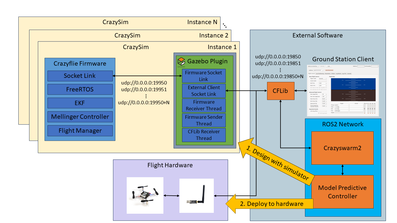
Last summer I began working with Crazyflies and noticed this Crazyflie simulator gap. I stumbled on a community-developed project for Crazyflie SITL called sim_cf. This project is exactly what I was looking for. However, the firmware used by the project is from July 2019 and the official firmware has had over 2000 commits made since then. The project also uses ROS 1, Gazebo Classic, and doesn’t support the Crazyflie Python library (CFLib). Using this project as a starting point I set out to develop CrazySim–a Crazyflie SITL project that doesn’t require ROS, uses Gazebo Sim, and supports connectivity through CFLib. Using CFLib we can connect the simulator to external software such as Crazyswarm2 or the Crazyflie ground station client. Users test their control algorithms in the external software using the simulator interface before deploying to real flight hardware.
An example of offboard model predictive control design and deployment workflow using CrazySim.
Using the Crazyflie Client for PID Tuning
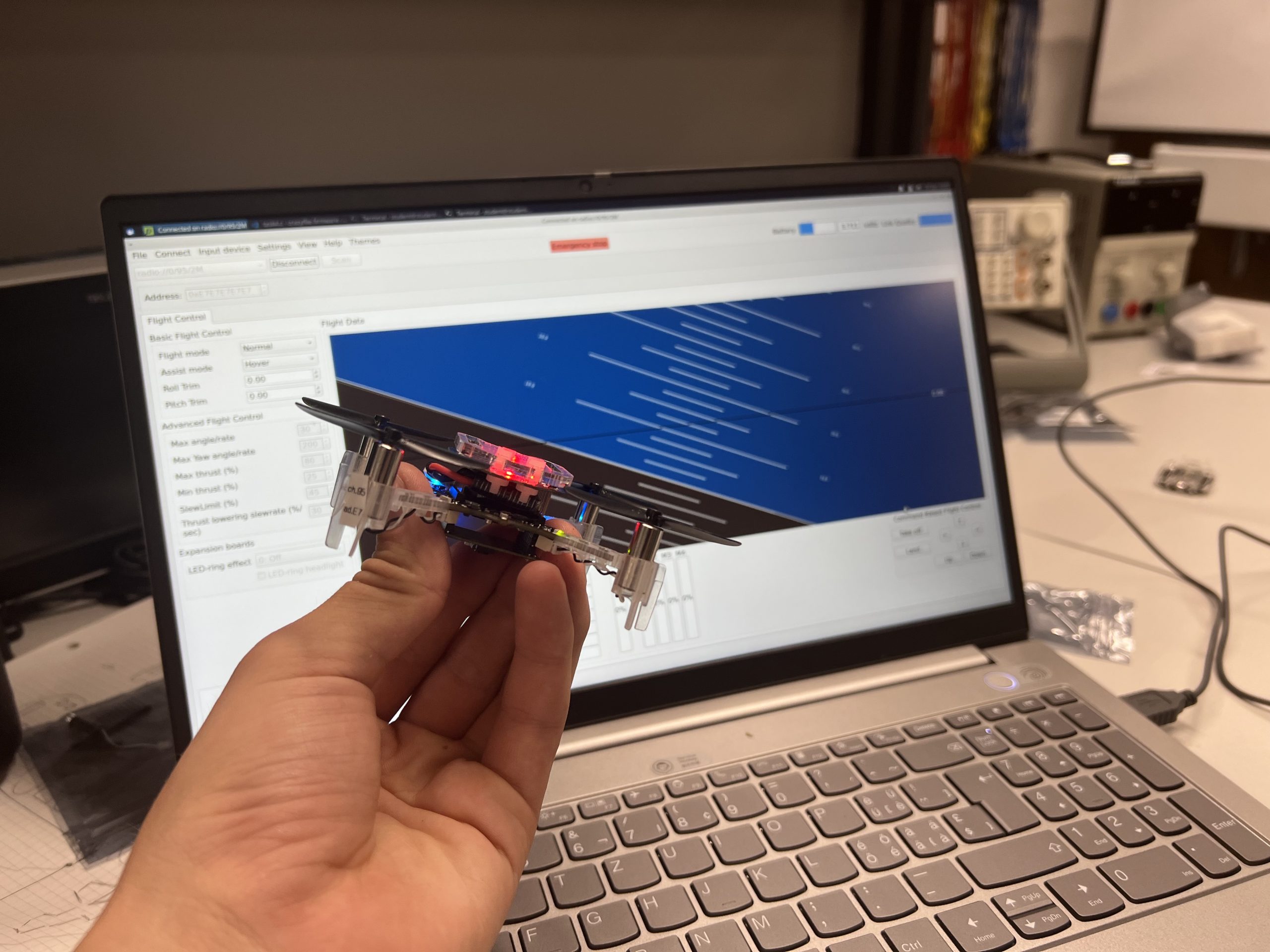
We have also provided a modified Crazyflie client for CrazySim support. The Crazyflie client is a cool tool for testing a single drone in hardware. We can perform command based flight control, look at real time plots, save log data, and tune PID values in real time. The PID values are typically tuned for an out of the box Crazyflie. However, when we modify the Crazyflie and add extra weight through batteries, decks, and upgraded thrust motors then the behavior of the Crazyflie will change. If a user wants to tune a custom Crazyflie setup, then they can add additional models in this folder with their own motor and mass properties. Then they just need to add it to the list of supported models in either of the launch scripts. There is already an example model for the thrust upgrade bundle. Documentation for installing the custom client can be found here.
PID tuning a simulated Crazyflie using CrazySim on the Crazyflie PC client.
Crazyswarm2
We can now connect to the simulated Crazyflie firmware using CFLib. Therefore, we can set up a ROS 2 interface through Crazyswarm2 for swarm command and control through ROS 2 topics and services. To do this we first startup the drones using any of the launch scripts.
Then, we bring up Crazyswarm2 after setting up the configuration file for the number of drones chosen.
ros2 launch crazyflie launch.py backend:=cflib
We demonstrate an example of how we can control a swarm of drones using Crazyswarm2 GoTo service commands.
Crazyswarm2 GoTo service commands using CrazySim.
ICRA 2024
CrazySim is also being presented as a paper at the 2024 IEEE International Conference on Robotics and Automation in Yokohama, Japan. If you are attending this conference and are interested in this work, then I invite you to my presentation and let me know that you are coming from this blog post after. For the paper, I created a multi agent decentralized model predictive controller (MPC) case study on ROS 2 to demonstrate the CrazySim simulation to hardware deployment workflow. Simulating larger swarms with MPC may require a high performance computer. The simulations in this work were performed on an AMD Ryzen 9 5950X desktop processor.
Model predictive control case study for ICRA 2024 paper.
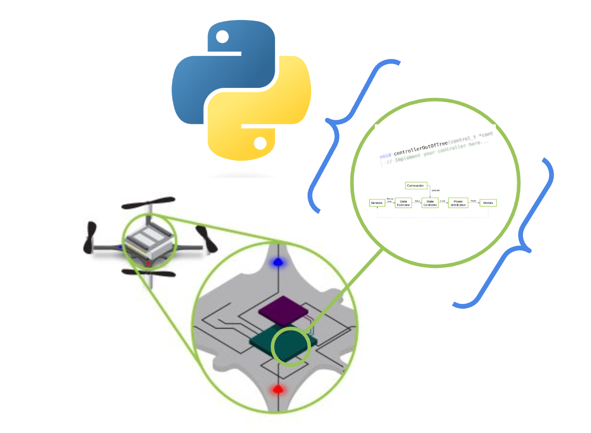
Today, we’d like to take the opportunity to spotlight a feature that’s been in our code base for some time, yet hasn’t been the subject of a blog post: the Python bindings for our Crazyflie firmware. You may have noticed it mentioned in previous blog posts, and now we’ll delve into more detail about what it is, how we and others are utilizing it, and what its future holds.
What are the Python bindings?
Language bindings, in essence, are libraries that encapsulate chunks of code, enabling one programming language to interface with another. For instance, consider the project Zenoh. Its core library is crafted in Rust, but it offers bindings/wrappings for numerous other languages like Python, C/C++, and so on. This allows Zenoh’s API to be utilized in scripts or executables written in those languages. This approach significantly broadens the functionality without necessitating the rewriting of code across multiple programs. A case in point from the realm of robotics is ROS(1), which initially created all of their APIs for different languages from scratch—a maintenance nightmare. To address this, for ROS 2, they developed the primary functionality entirely in C and provided wrappers for all other programming languages. This strategy eliminates the need to ‘reinvent the wheel’ with each iteration.
Rather than redeveloping the firmware in Python, our esteemed collaborators Wolfgang Hönig and James Preiss took a pragmatic approach. They selected parts of the Crazyflie firmware and wrapped them for Python use. You can see the process in this ticket. This was a crucial step for the simulation of the original Crazyswarm (ROS1) project and was continued for its use in the Crazyswarm2 project, which is based on ROS 2. They opted for SWIG, a tool specifically designed to wrap C or C++ programs for use with higher-level target languages. This includes not only Python, but also C#, GO, Javascript, and more, making it the clear choice for implementing those bindings at the time. We also strongly recommend checking out a previous blogpost by Simon D. Levy, who used Haskell to wrap the C-based Crazyflie Firmware for C++.
Where are the Python bindings being used?
As previously mentioned, the Crazyswarm1 & 2 projects heavily utilize Python bindings for testing key components of the firmware (such as the high-level commander, planner, and controller) and for a (hybrid) software-in-the-loop simulation. During the project’s installation, these Python bindings must be compiled so they can be used during simulation. This approach allows users to first test their trajectories in a simulated environment before deploying them on actual Crazyflies. The advantage is that minimal or no modifications are required to achieve the same results. While simulations do not perfectly mirror real-world conditions, they are beneficial because they operate with the same controller as the one used on the Crazyflie itself. In our own Crazyflie simulation in Webots, it’s also possible to use these same bindings in the simulator by following these instructions.
Three controllers (PID, Mellinger, and Brescianini), intra-drone collision avoidance, and the high-level commander planner have all been converted into Python bindings. Recently, we’ve added a new component: the Extended Kalman Filter (EKF). This addition is ideal as it allows us to test the filter with recorded data from a real Crazyflie and experiment with different measurement models. As we discussed in a previous blogpost, estimators are complex due to their dependence on chance and environmental factors. It’s beneficial for developers to have more control over the inputs and expected outputs. However, the EKF is deeply integrated into the interconnected processes within the Crazyflie Firmware. After a significant refactoring effort, these were added to the bindings by creating an EKF emulator (see this PR). This enabled Kristoffer to further enhance the TDOA outlier filter for the Crazyflie by emulating the full process of the EKF, including IMU data.
In addition to SITL simulation and EKF development, Python bindings are also invaluable for continuous integration. They enable comprehensive testing that encompasses not just isolated code snippets, but entire processes. For instance, if there’s a recording of a Crazyflie flight complete with sensor data (such as flow, height, and IMU data), and it’s supplemented with a recorded ground truth (from lighthouse/mocap), this sensor data can be fed into the EKF Python binding. We can then compare the outputted pose with the ground truth to verify accuracy. The same principle applies to the controllers. Consequently, if any changes are made to the firmware that affect these crucial aspects of Crazyflie flight, these tests can readily detect them.
If you like to try the python bindings tests for yourself, clone the Crazyflie-firmware repo and build/install the python bindings via these instructions. Make sure you are in the root of the repository and run: python3 -m pytest test_python/. Mind that you might need to put the bindings in the same path with export PYTHONPATH=<PATH_TO_>/crazyflie-firmware/build:$PYTHONPATH (please see this open ticket)
The next steps of the python bindings
We’ve seen how Python bindings have proven to be extremely useful, and we’re keen to further expand their application. At present, only the Loco positioning system has been incorporated into the EKF part of the Python bindings. Work is now underway to enable this for the Lighthouse system (see this draft PR). Incorporating the Lighthouse system will be somewhat more complex, but fortunately, much of the groundwork has already been laid, so we hope it won’t be too challenging. However, we have encountered issues when using the controller bindings with simulation (see this open ticket). It appears that some hardware-specific timing has been hardcoded throughout the PID controller in particular. Therefore, work needs to be done to separate the hardware abstraction from the code, necessitating additional refactoring work for the controller.
Recent projects like Sim_CF2 (see this blogpost) and Crazysim (see this discussion thread) have successfully compiled the Crazyflie firmware to run as a standalone node on a computer. This allows users to connect it to the Crazyflie Python library as if it were an actual Crazyflie. This full Software-In-The-Loop (SITL) functionality, already possible with autopilot suites like PX4 and Ardupilot, is something we at Bitcraze are eager to implement as well. However, considering the extensive work required by the aforementioned SITL projects to truly separate the hardware abstraction layer from the codebase, we anticipate that refactoring the entire firmware will be a substantial task. We’re excited to see what we can achieve in this area.
Indeed, even with a more comprehensive Software-In-The-Loop (SITL) solution, there’s no reason to completely abandon Python bindings. For developments requiring more input/output control—such as the creation of a new controller or an addition to the Extended Kalman Filter (EKF)—it’s beneficial to start with just that portion of the firmware code. Python bindings and a SITL build can coexist, each offering its own advantages and disadvantages for different stages of the development process. By leveraging the tools at our disposal, we can minimize the risk of damaging Crazyflies during development. Let’s continue to make the most of these valuable resources!
Dumping and loading persistent parameters to and from a file
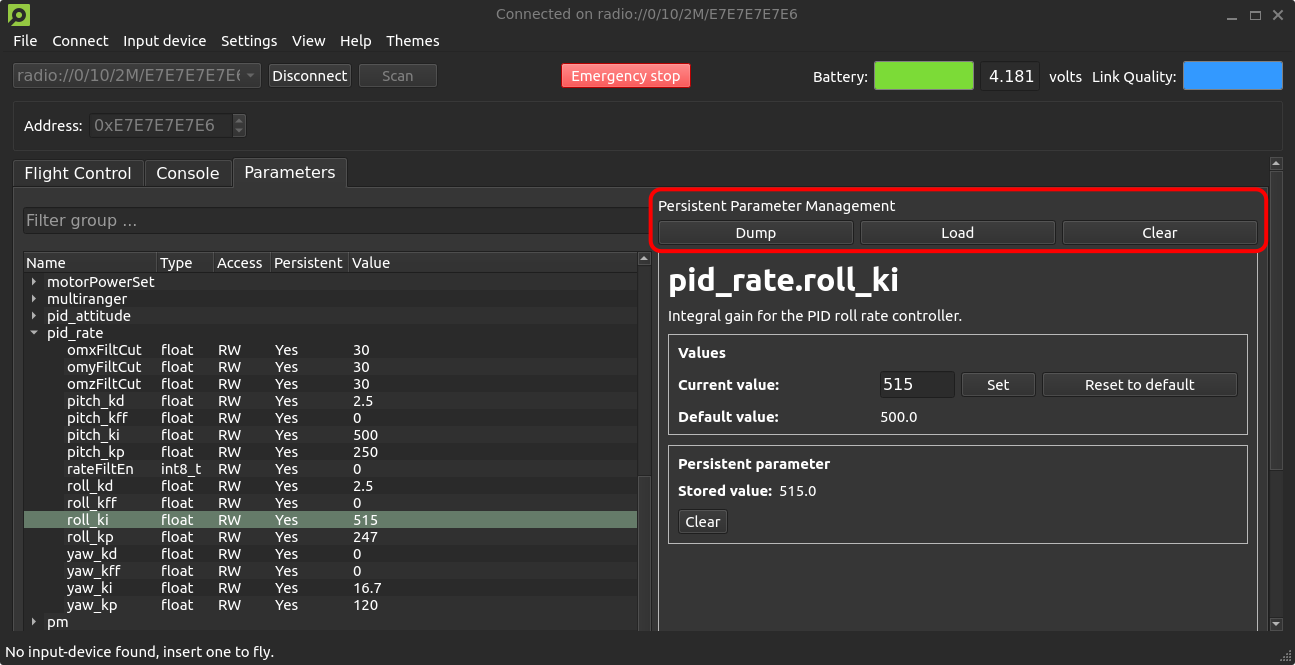
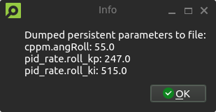
We have a small quality-of-life update that will allow users to dump and load persistent parameters to and from a file that has recently been merged #PR443 and #PR706. A new persistent parameter management area is introduced to the parameters tab of the client, with buttons for dumping and loading persistent parameters, as well as clearing all stored persistent parameters from the Crazyflie. The persistent parameters are stored in .yml format, allowing for manual editing if desired. If you have any improvement suggestions please drop us a comment!
A new persistent parameter management area is introduced to the parameters tab of the client, with buttons for dumping, loading and clearing stored persistent parameters.An information dialog notifies users of the dumped persistent parameters and their values. Loading parameters will result in a similar pop-up.A confirmation dialog prevents accidental clearing of persistent parameters.
System-id code merged to master
Back in 2021, we created the system-id deck which we talked about in this blog post. It has not been officially released but a few users have gotten some PCBs and built it themselves. The functionality for the system-id deck has previously been in a branch, but as code in branches tends to become outdated, we have now moved this into the master branch utilizing the kbuild system instead. Building for the system-id deck is now as easy as doing “make sysid_defconfig” and then compiling. While talking about the system-id deck, let’s check the interest of releasing it as a product. It can help with system identification, tuning of controllers, improving efficiency etc. With enough interest there might be an economy in manufacturing it.
Out of stock
Unfortunately, we’re out of stock of Crazyflies at the moment. We expect some at the end of next week, so hopefully, you should be able to find them back in the store quickly.
Developer meeting
The next developer meeting will be on the 6th of March 2024, Arnaud will talk about the Crazyflie Client past, present and future, based on its last blog post. The client is still very useful but starts to show its age so we are looking at what should be kept, what should be improved and what should be removed. We will present what we have in mind, please come and discuss with us so we can shape the next 10 years of Crazyflie client!
The Crazyflie client has a quite long history, like a lot of things in the Crazyflie ecosystem it has been started when the Crazyflie was used alone using mainly manual control. It has evolved to follow new use-cases of the Crazyflie but it still has traces of its origins and some limitation are still there with us. Moreover, the Crazyflie client and lib are written in python, one the main goal was to make it easily cross-platform. Unfortunately making a cross platform graphical program that accesses hardware in Python has proven to be quite challenging and we feel Python is not the way to go anymore. In this blog post we would like to discuss a bit the current state of the Client and what we are looking at for the future.
A Crazyflie connected to the CFclient
The Crazyflie client was originally design to be able to fly, inspect and work with one Crazyflie. It still serves this purpose quite well: with the client you can connect your Crazyflie, observe graphs of internal log values in real time, setup different decks and sets and store parameters. It is a very good tool to explore and work with the Crazyflie.
However, it is only working with one Crazyflie at a time will take over the radio, so another script cannot talk to the Crazyflie at the same time using the radio. Unless the script uses the ZMQ API that allows an external program to control client and so to control the Crazyflie while the client is connected and active. This functionality can be very useful but, since it is disabled by default, has not seen a lot of use.
The worst, for us, in the current client state is Python and PyQT distribution situation: we used to have an easy-to-use installer on windows, a Linux Snap package and plan for a Mac App. All these have been pretty much abandoned because they kept breaking down over time and the support weight for us was too big. So the only way to install the client is via Pip, the python package manager. This means that you already need a well setup Python environment to run the client. That is nice unless you have a Mac or a Raspberry pi: the latest MacOS broke part of the client that prevents it to run and there is no PyQT build for raspberry-pi available on PyPi. This is the kind of paper-cut that keeps happening at regular interval with distributing a Python application and that we keep having to look at.
So, we have been looking at ways to improve the situation. The Crazyflie client is more than 10 years old now, so a rewrite would not be such a crazy thing to consider. There are at least 2 angle of attack to make a new client better suited for the next 10 years of Crazyflie development:
Multi-platform and distribution
Making a multi-platform program is and will always be challenging. However, we have discovered that doing it in a dynamic interpreted language like python is even more so. The main challenge come from the fact that things tend to break on the user side depending of the user configuration: we all run a slightly different version of python, python evolve and package management evolves as well, so when things break it breaks at random depending of how up-to-date a particular system.
One solution would then be to switch to a compiled programming language. This increases the probability of finding problem at compile time and not at runtime, which means that we will hopefully be the first to know then Apple decided to change the location of one fundamental piece of library and so allow us to hopefully fix the problem before any user is impacted (assuming we can run CI on the latest version of MacOS early enough…).
So, as you might have guessed, our current idea is to write the client in Rust. We are currently looking at Tauri for the UI which is Web based. We still have ideas of also making a web-client so having a web-based IU on PC would simplify development of that.
We are not letting Python go away though, the idea is still to support Python, but to use it for what it is good at: a great language for developer and experimentation. Rust has great bindings to python so in this plan, the python lib is backed by the Rust lib.
Modularity
The other side of the current client limitation is the fact that it connects one Crazyflie taking over the radio. We actually love using the client to observe and poke the state of a Crazyflie so it would be really great to use it when writing a script or controlling a swarm with Crazyswarm. The current ZMQ implementation was designed to solve this issue, but it goes at it the wrong way around: the client becomes the gateway to the Crazyflie and must always be ON. It would be much nicer to be able to launch the client to connect and inspect a Crazyflie currently control by a script.
One design we are currently looking at would be to use use a protocol like Zenoh between the client and the lib. Basically, when connecting a Crazyflie, be it from a script or from the client, a server would be launched in the background that would handle the connection. All communication would pass through this server and so multiple programs would be able to communicate simultaneously with the Crazyflie.
This would allow us to build easily bridges to ROS to get the client to communicate with a Crazyflie currently connected in ROS. And since ROS2 is working on supporting Zenoh officially a bridge might not even be required.
As an added bonus, the Crazyflie server idea would greatly improve the situation when it comes to supporting Virtual Machines and WSL on Windows: it would move the USB connection handling to a Windows program and only require fast network connections which is something that works really well on WSL or VMs.
Conclusion
In this blog post I have tried to describe our current challenges and some way forward we see. The main message though is that we want to change things when it comes to the client, if you have wishes or ideas now is a good time to get in touch. Let’s make the next 10 years of Crazyflie client problem-free.
Today we have a guest blogpost by Simon D. Levy (Washington and Lee University) about using Haskell to warp parts of the Crazylife-firmware. We also have some announcements from Bitcraze itself at the bottom. Enjoy!
As Richard Feynman famously said, What I cannot create, I do not understand. My less ambitious version of this motto is What I can translate into another language, I might better understand.
In order to better understand the Crazyflie firmware, I first undertook to translate the C-based firmware into C++. By separating out the general-purpose algorithmic code (state estimator, closed-loop control) from the Crazyflie-specific / Hardware Abstraction Layer (HAL) component of the firmware, I ended up with a nice, header-only C++ library of algorithms that can work with both a simulator like Webots and on a Crazyflie 2.1 or Crazyflie Bolt flight controller (with the remaining Crazyflie firmware translated into the standard C++ .h/cpp format).
As a fan of functional languages like OCAML and Haskell (and Rust, which was strongly influenced by their approach), I wondered whether I couldn’t push this idea further, to get an even higher-level implementation of the algorithms. Having played a bit with Rust and encountered issues getting it to work efficiently with C++ (something that is thankfully now being addressed), I thought it might be work trying NASA Copilot, a Haskell extension that compiles Haskell into C with a fixed memory footprint (i.e., no malloc() or garbage-collection).
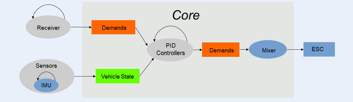
My efforts paid off, resulting in a Haskell library of algorithms for closed-loop (PID) control and motor mixing that works with both my modified version of the Crazyflie firmware and with a simulator like Webots. For anyone wondering “why Haskell”, I refer you to this excellent discussion on the language’s advantages (purity, elegance), as well as this classic presentation on why the functional programming offers a better solution to complex tasks than object-oriented approach. For example, the code in the LambdaFlight core module cleanly reflects the dataflow (input/output) diagram for a standard flight controller:
Here is the Haskell code corresponding the component labeled Core in the diagram:
— Clock rate is 500Hz for Crazyflie, 100Hz for sim
dt = rateToPeriod clock_rate
— Make a list of PID controllers based on application order
pids = [positionPid resetPids inHoverMode dt,
pitchRollAnglePid resetPids inHoverMode dt,
pitchRollRatePid resetPids inHoverMode dt,
altitudePid inHoverMode dt,
climbRatePid inHoverMode dt,
yawAnglePid dt,
yawRatePid dt]
— Run PID controllers on open-loop (stick) demands to get demands for motor mixer
demands’ = foldl (\demand pid -> pid vehicleState demand) openLoopDemands pids
— Adjust thrust component for hover mode
thrust” = if inHoverMode then ((thrust demands’) * tscale + tbase) else tmin
— Run motor mixer on closed-loop demands to get motor spins, scaled for CF or sim
motors = quadCFMixer $ Demands thrust”
((roll demands’) * prscale)
((pitch demands’) * prscale)
((yaw demands’) * yscale)
By adjusting the values of the clock rate and scaling coefficients (tscale, tbase, prscale, …), the same PID controllers (with same Kp, Ki, Kd constants) can be used for both the simulation and the actual Crazyflie.
Two pieces complete the picture.
First, how can a pure functional language like Haskell, lacking mutation/side-effects, support an algorithm like PID control, which requires keeping state variables (error integral, previous error) across iterations? The answer to this question comes from an ingenious part of the NASA Copilot framework, namely, streams. A stream (which is similar to a lazy list in Haskell), can come from an module of the program written in C (for example, the vehicle state obtained by state estimation) or from a previous value passed into the function. This feature allows Copilot to have functions that possess state while still being “pure” in the sense of being amenable to formal verification (mathematical proof of correctness; see this thread for a discussion). Although I don’t have the mathematical background to do formal verification proofs, the ability to prove the code correct is an extremely powerful feature of languages like Haskell and is what led NASA to develop the Copilot framework for its space missions.
Second, how can Haskell be combined with C/C++ without running into the performance issues typically encountered in calling code in one language from code in another? As I alluded to before, NASA Copilot solves this issue nicely, by compiling the Haskell code to C code with a fixed memory footprint. Declaring certain C/C++ variables to be global makes them accessible to the Haskell code as streams, and causes them to be compiled into the resulting C code, which can then be compiled and linked to the Crazyflie (or simulator) C/C++ code in the usual way (thanks to the Crazyflie Makefile’s use of the Kbuild system). Hence, to compile the whole project into a form suitable for flashing with make cload, requires just the following chain of commands (where make links creates links to some external libraries I wrote for the sensors):
make cf2_defconfig && make links && make copilot && make -j 32
My current work focuses on two directions: first, I am translating Crazyflie’s Kalman filter into Haskell — a more ambitious undertaking, but one that I feel more confident in undertaking now that the core control algorithms are completed. Second, I am looking for ways of modifying the most popular robotics simulators (Webots, Gazbeo) to work with dynamics (physics engine) code custom-written for quadcopters and other aerial vehicles (like the dynamics code I wrote for this simulator), as well as faster control loops.
Announcements
There are some announcements that are not part of this guest blogpost that we’d like to share.
The 350 mAh batteries are out of stock and unfortunately have a very long lead time at our manufacturer, so you can expect them to be back in stock early May. Please take a look this blogpost which also compares this battery to the Tattu alternative, if you can’t wait and need to have a similar battery now.
We have a Bitcraze developer meeting this Wednesday to talk about the supervisor safety functionalities in the crazyflie-firmware. Please keep an eye on the GH discussion thread for information on how to join.
There is a new release of the firmware, version 2024.2. The main change, and almost only change, in this release, is the Bluetooth stack that was updated from the Nordic’s semiconductor S110 to S130, which affects the firmware on the NRF51 on the Crazyflie. This was mainly done to be able to pass the listing requirement on Bluetooth SIG, but it will also have beneficial technical effects on the Crazyflie radio communication state of affairs.
The new stack and bootloader are distributed in the normal release .zip, which means that it can be updated from the client as normal. Please note that the latest lib and clients are required as we have had to implement new procedures to flash the bootloader and stack.
First of all, let’s define what is a soft device. Nordic semiconductor radio chips are awesome in the way that the radio hardware is fully documented, this means that we can implement our own radio protocols but we would also be able to implement our own Bluetooth stack (I have attempted that a long time ago with some success, the nRF5 radio hardware is really powerful and can be set up to do much of the work!). However, backing your own Bluetooth stack would require passing a full suite of validation at the Bluetooth SIG to prove the stack conform to specification. In order to avoid that, the usual strategy is to buy a Bluetooth device and to talk to it over UART. What Nordic did is to implement a “Softdevice”, a binary blob that runs in the same CPU as the user application and that talks to the application using software interrupt. This keeps the application completely separated from the Bluetooth stack and so means that we get the benefits of a pre-qualified Bluetooth stack that has already been tested and approved.
Currently, we have ported the bootloader and the nrf firmware to the new S130 stack. This opens a lot of potential benefits for the future:
The new stack should be at least 6 times faster than the old one. This makes implementing BLE communication for the Crazyflie to a PC/Chromebook much more appealing and should allow to make the existing mobile client more full features.
We are now able to update the bootloader, so we can make a new improved version of it in the future (ie. with safe link, swarm optimization, much faster Bluetooth boot loading….)
The new stack supports device and host mode. So things like pairing a gamepad with the Crazyflie becomes a technical possibility! (actual implementation is left as an exercise for the contributor ;-).
One very important thing to note is that working on the bootloader requires a debugger: if you flash a bugged radio bootloader you need a SWD debug probe to be able to fix your Crazyflie. The bootloader+softdevice flashing procedure is very safe, as long as you flash a working firmware.
This change should open quite new exciting possibilities. It will be interesting to see what we can achieve with BLE and updated bootloaders in the future. Please note that we had to make a change to both the Crazyflie python library and the CFclient in order to flash this new firmware so make sure that you update those as well to try out this new release.
Developer meeting
The next developer meeting will be on the 6th of March 2024, we will talk about the Crazyflie Supervisor subsystem… We have made some changes to the supervisor recently, and we will continue working more on it in the next couple of weeks mostly preparing for the arrival of the Brushless Crazyflie. We will talk about the current state and what we are working on. Follow the thread on Bitcraze Discussions to be up to date on how to join!
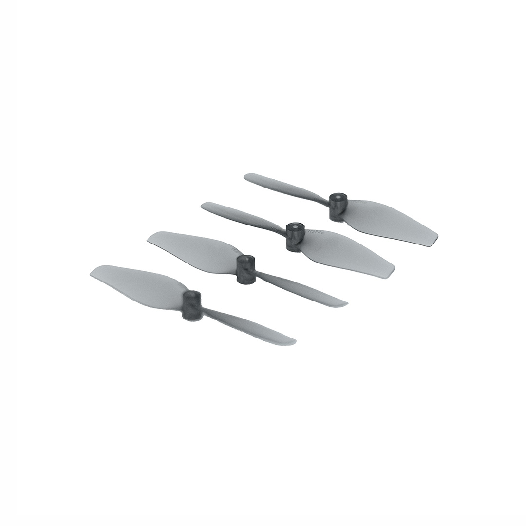
You may have noticed that the HQ propellers, which are a part of the thrust upgrade bundle, have been out of stock for quite some time now. I know that many of you are relying on those propellers for the additional 20 grams of thrust they allow, so I have some news – some good, some bad.
Let’s start with the bad news: our partner and manufacturer, unfortunately, faced some problems with the mold they were using for these propellers- we prepared to face the fact that having our thrust propellers as they were before was not possible anymore. With the mold in this state, we could never go back to the same version of those propellers. To be a little dramatic, the high-quality propellers have taken their final spin. We knew it could take some time to find a good solution, and were prepared to communicate about a long-time shortage of the item.
But now for the good news! Thankfully, the replacement mold our partner used proved to be as good as the previous one – and faster than scheduled. Now back in stock, the HQ propeller can fly as well as its predecessor. We tested it and it showed the same characteristics that we’ve come to expect from the thrust upgrade.
So, what’s the real difference? Well, since it maintains the same level of performance, agility, and stability, not much. They have an updated design and have an added “ultralight” in the name (which sounds cooler, doesn’t it?). Those of you with a keen sense of observation will also notice that they have a new SKU – as well as the thrust upgrade bundle.
All in all, this change will have minimal impact on your flying if you’re used to the thrust upgrade bundle. Don’t hesitate to try out this new version and give us some feedback if you have any!
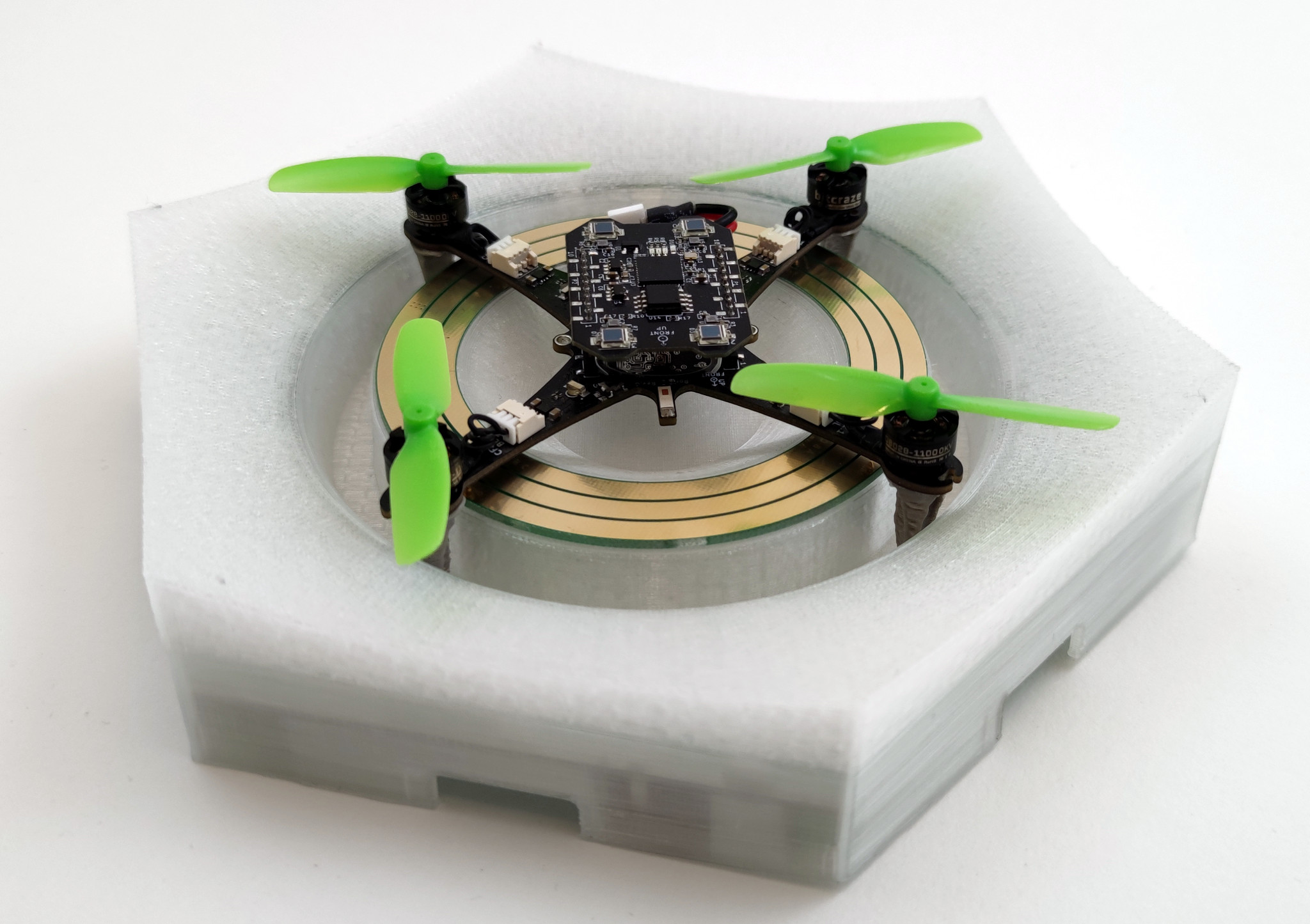
If you haven’t seen it yet then check out our latest Christmas video! In it, we show off a bunch of new stuff, with the main ones being the new Crazyflie brushless and the Lighthouse V2 (which supports up to 16 base stations). But there were also a few other things featured in the video! One of them is the charging pad the Crazyflie brushless takes off from and lands on in the video. This weeks blog post is about the charger, how it came to be, how it works and what lies ahead.
Some history
A while back I worked a bit on a contact charger for the Crazyflie 2.1. The idea was to try and make a design where small pogo-pins could be added to various decks which would allow the Crazyflie 2.1 to charge when lading on a charging pad. Some of the issues with the design was that the area was small (it had to fit on a deck), it put requirements on each deck and that some decks (like the Flow V2 deck) has components which are taller than the pogo-pins. So after the blog post back in 2021 this has been on the shelf, until recently when the Crazyflie brushless work has been moving forward.
With the new prototype design for the Crazyflie brushless being made, there was a chance to address some of the issues I’ve seen before and do another try. All we needed was to add some pads for soldering pogo-pins on the wings (which actually wasn’t as easy as one would think due to layout constraints). So now the charging points didn’t have to be on each deck, they are built into the Crazyflie BL base. The distance between the points is also larger, allowing for a bigger hole in the charging PCB and allowing for a higher variety of decks, like the LED ring with the diffuser shown in the video.
The last missing part of the puzzle was when we needed to do more flight testing with the Crazyflie brushless. We wanted to reproduce the infinite flight demo we previously had for the Crazyflie 2.1, but the current Qi charger pad didn’t work with the new Crazyflie brushless. Time for the next iteration of the charger prototype!
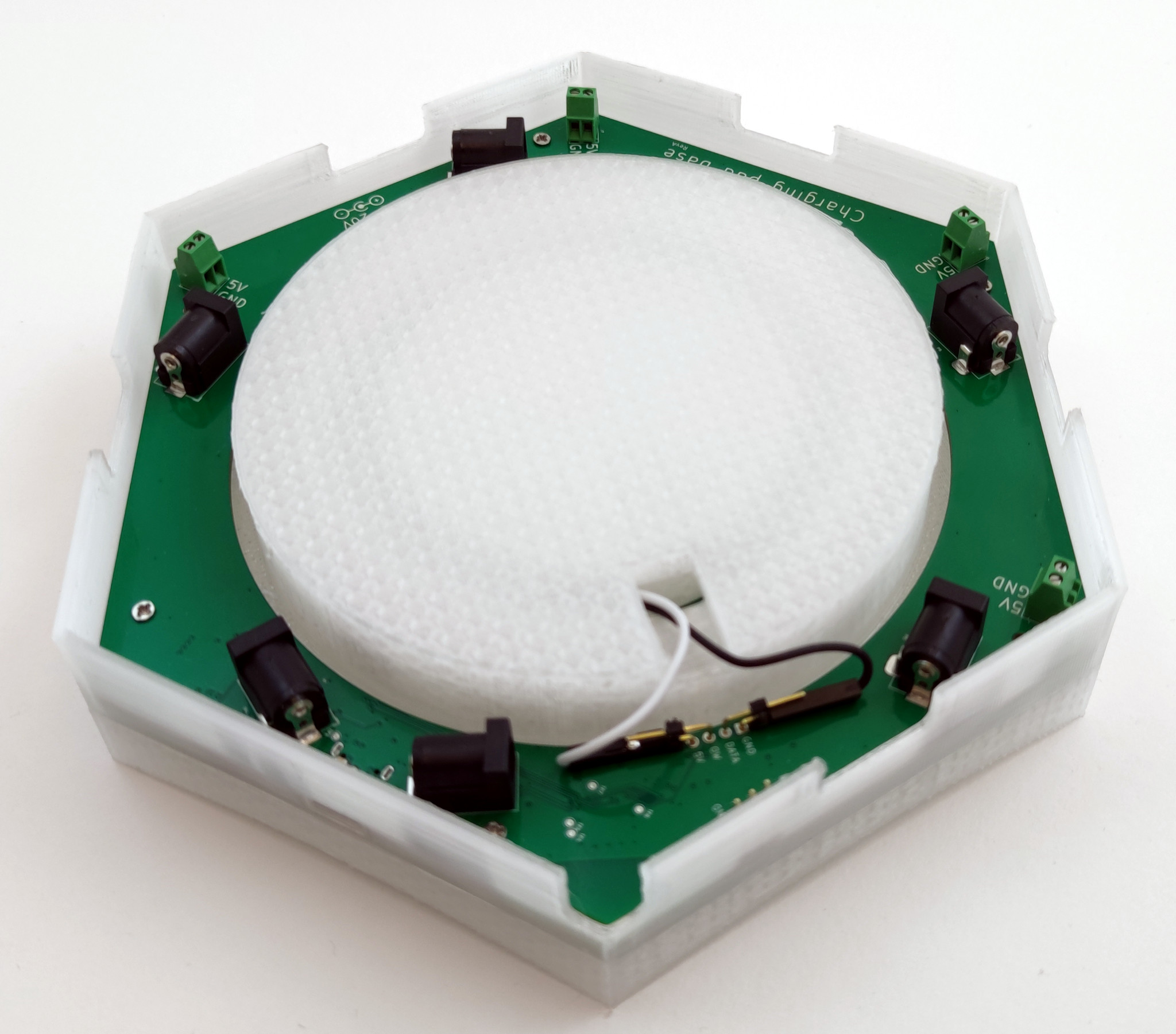
Under the hood
So how complex can you make a charger? Lots! When making a prototype I like to add as much ideas possible to the design. Missing something you wanted to test and doing a new version takes a lot of time but adding some extra crazy ideas might be pretty quick in the design phase. A lot of the time ideas are scrapped along the way, most of the time because of space- or price constraints. Sometimes they are just bad or too complex. Luckily in this case the charger has a large PCB with lots of space and it’s just an early prototype so there’s (almost) no bad ideas!
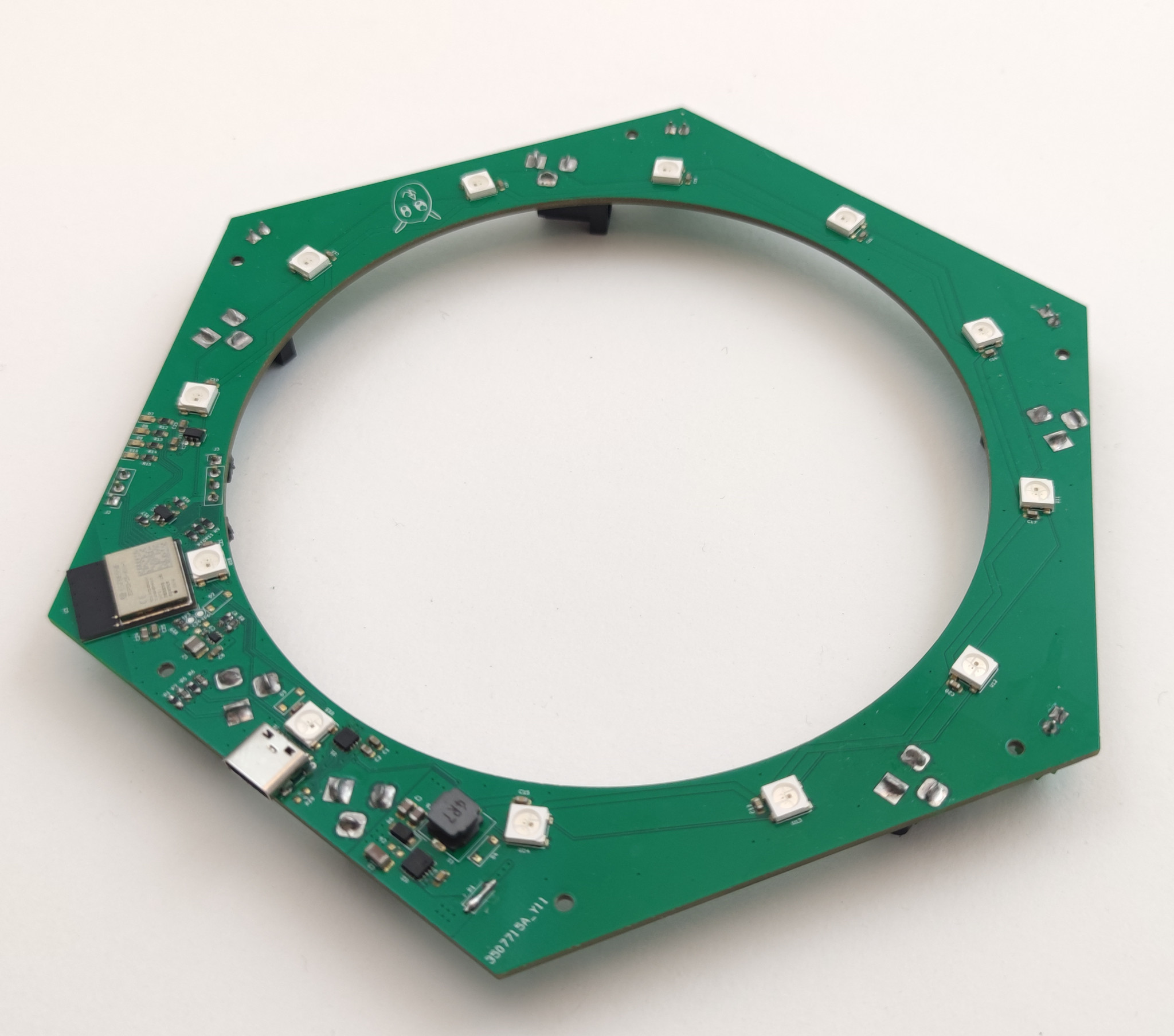
Under the hood (or 3D printed plastic in this case) there’s a bunch of stuff:
An WiFi/BLE module, the ESP32-C6-MINI
USB-C connector
USB-PD controller
6 DC-jack connectors and 5 terminals for connecting power
Measurement of charging current and supply voltage
12 WS2812B RGB LEDs for the outer ring and 12 for the inner one
20-to-5V DC/DC and 5-to-3V3 DC/DC
Some debugging LEDs and UART
Intended use
The idea with the contact charger has been to easily charge your Crazyflie without disconnecting the battery, plugging in the micro-USB connector or blocking the use of decks facing downwards like the Qi charger does. In addition to this I also wanted to try out some other ideas.
WiFi: For a long time I’ve had a prototype of a server for connecting various hardware to (like a charger) so I wanted to try to connect it to this for monitoring.
BLE: The idea was that the Crazyflie could talk to the charger via BLE to for instance change the light effect.
LEDs (and lots of them): The idea was to give some feedback from the charging of the Crazyflie but also to give the charger the ability to act as something more, like lighting up when a Crazyflie decides to land on it.
USB-PD: This is connected to the chaining of power. The ideas was to connect a USB-C charger and distribute the power from it to other chargers via the DC-jack.
Rust: Like we’ve written about before, we’ve been trying out more and more Rust here at Bitcraze. This is yet another experiment, the firmware for the charger is written in Rust using Embassy.
Future
Currently the charger is an internal project, since we use it in our lab for the infinite flight. But it’s of course something that would be exciting to offer our users if there any interest. So let us know what you think!
Also, don’t forget to join us for this Wednesday’s dev meeting. the main topic will be about the Kalman filters however we can answer questions about the wireless as well!
However, we have noticed that some of our beginning users struggle with understanding the concept of Kalman filtering, depending on whether this has been covered in their curriculum. And for some more experienced users, it might be nice to have a recap of the basics as well, since this is a very important part of the Crazyflie’s capabilities of flight (and also for robotics in general). So, in this blog post, we will explain the principles of Kalman filtering and how it is applied within the Crazyflie firmware, which hopefully will provide a good base for anyone starting to delve into state estimation within the Crazyflie.
Anybody remotely working with autonomous systems must, at one point, have heard of the Kalman filter, as it has existed since the 60s and even played a role in the Apollo program. Understanding its main principles is also important for anyone working with drones or robotics. There are plenty of resources available, and its Wikipedia page is filled with examples, so here we will focus mostly on the concept and principles and leave the bulk of the mathematics as an exercise for those who like to delve into that :).
So basically, there are several principles that apply to a Kalman filter:
It estimates a linear system that is driven by stochastic processes. The probability function that drives these stochastic processes should ideally be Gaussian.
It makes use of the Bayes’ rule, which is a general term in statistics that describes the probability of an event happening based on previous knowledge related to that event.
It assumes that the ‘to be estimated state’ can be described with a Markov model, which assumes that a sequence of the next possible event (or scenario) can be predicted by the current event. In other words, it does not need a full history of events to predict the next step(s), only the information from the event of one previous step.
A Kalman filter is described as a recursive filter, which means that it reuses (part of) its output as input for the next filtering step.
So the state estimate is usually a vector of different variables that the developer or user of the system likes to observe, for either control or prediction, something like position and velocity, for instance: [x, y, ẋ, ẏ, …]. One can describe a dynamics model that can predict the state in the next step using only the current time step’s state, like for instance: xt+1 = xt + ẋt, yt+1 = yt + ẏt. This can also be nicely described in matrix form as well if you like linear algebra. To this model, you can also add predicted noise to make it more realistic, or the effect of the input commands to the system (like voltage to motors). We will not go into the latter in this blogpost.
The Concept of Kalman filters
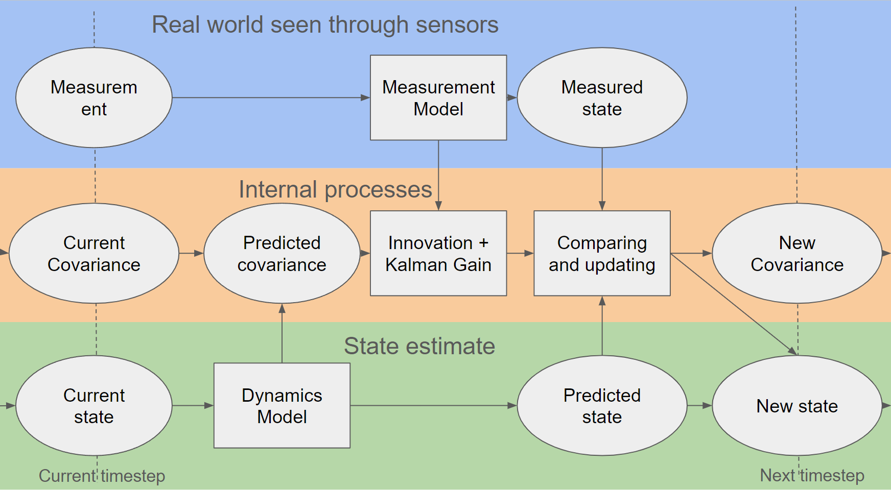
Simplified block scheme of Kalman filtering
So, we will go through the process of explaining the steps of the Kalman filter now, which hopefully will be clear with the above picture. As mentioned before, we’d like to avoid formulas and are oversimplifying some parts to make it as clear as possible (hopefully…).
First, there is the predict phase, where the current state (estimate) and a dynamics model (also known as the state transition model) result in a predicted state. Also in the same phase, the predicted estimated covariance is calculated, which also uses the dynamics model plus an indication of the process noise model, indicating how much the dynamics model deviates from reality in predicting that state. In an ideal world and with an ideal model, this could be enough; however, no dynamics model is perfect, which is why the next phase is also very important.
Then it’s the update phase, where the filter estimate gets updated by a measurement of the real world through sensors. The measurement needs to go through a measurement model, which transforms the measurement into a measured state (also known as innovation or measurement pre-fit residual). Usually, a measurement is not a 1-1 depiction of one variable of the state, so the measurement model ensures that the measurement can properly be compared to the predicted state. This same measurement model, accompanied by the measurement noise model (which indicates how much the measurement differs from the real world), together with the predicted covariance, is used to calculate the innovation and Kalman gain.
The last part of the update phase is where the predictions are updated with the innovation. The Kalman gain is then used to update the predicted state to a new estimated state with the measured state. The same Kalman gain is also used to update the covariance, which can be used for the next time step.
An 1D example, height estimation
It’s always good to show the filter in some form of example, so let’s show you a simple one in terms of height estimation to demonstrate its implications.
1D example of height estimation
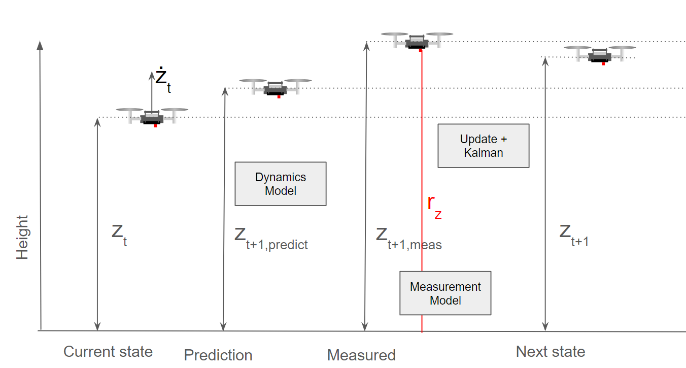
You see here a Crazyflie flying, and currently it has its height estimated at zt and its velocity at żt. It goes to the predict phase and predicts the next height to be at zt+1,predict, which is a simple model of just zt + żt. Then for the innovation and updating phase, a measurement (from a range sensor) rz is used for the filter, which is translated to zt+1, meas. In this case, the measurement model is very simple when flying over a flat surface, as it probably is only a translation addition of the sensor to the middle of the Crazyflie, or perhaps a compensation for a roll or pitch rotation.
In the background, the covariances are updated and the Kalman gain is calculated, and based on zt+1,predict and zt+1, meas, the next state zt+1 is calculated. As you probably noticed, there was a discrepancy between the predicted height and measured height, which could be due to the fact that the dynamics model couldn’t correctly predict the height. Perhaps a PID gain was higher than expected or the Crazyflie had upgraded motors that made it climb faster on takeoff. As you can see here, the filter put the estimated height closer to zt+1 to the measurement than the predicted height. The measurement noise model incorporated into the covariances indicates that the height sensor is more accurate than the height coming from the dynamics model. This would very well be the case for an infrared height sensor like the one on the Flow Deck; however, if it were an ultrasound-based sensor or barometer instead (which are much noisier), then the predicted height would be closer to the one predicted by the dynamics model.
Also, it’s good to note that the dynamics model does not currently include the motor input, but it could have done so as well. In that case, it would have been better able to predict the jump it missed now.
A 2D example, horizontal position
A 2D example in x and y position
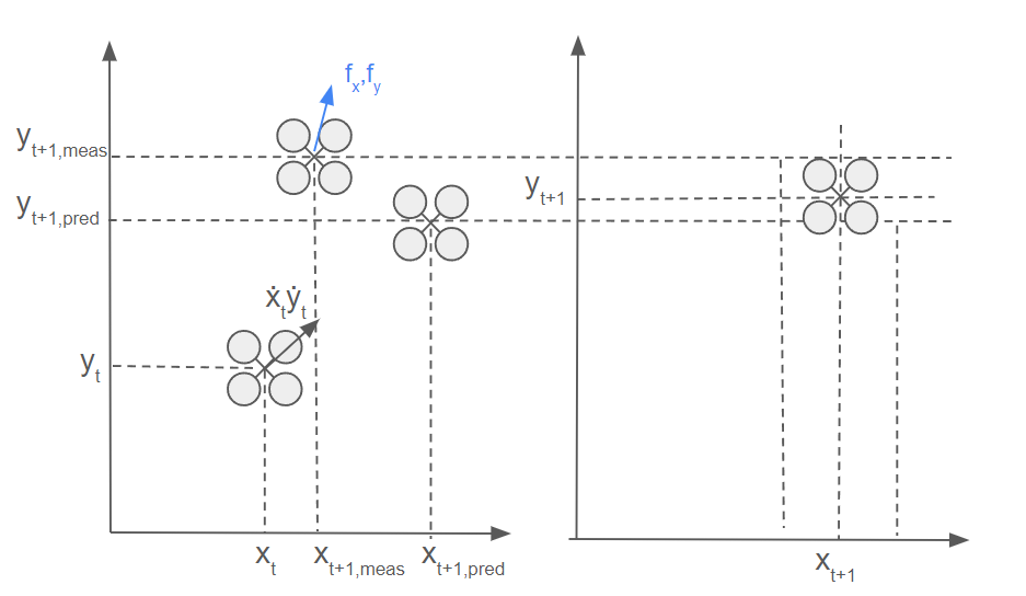
Let’s take it up a notch and add an extra dimension. You see here now that there is a 2D solution of the Crazyflie moving horizontally. It is at position xt, yt and has a velocity of ẋt, ẏt at that moment in time. The dynamics model estimates the Crazyflie to end up in the general direction of the velocity factor, so it is a simple addition of the current position and velocity vector. If the Crazyflie has a flow sensor (like on the Flow Deck), flow fx, fy can be detected and translated by the measurement model to a measured velocity (part of the state filter) by combining it with a height measurement and camera characteristics.
However, the measurement in the form of the measured flow fx, fy estimates that there is much more flow detected in the x-direction than in the y-direction. This can be due to a sudden wind gust in the y-direction, which the dynamics model couldn’t accurately predict, or the fact that there weren’t as many features on the surface in the y-direction, making it more difficult for the flow sensor to measure the flow in that direction. Since this is not something that both models can account for, the filter will, based on the Kalman gain and covariances, put the estimate somewhere in between. However, this is of course dependent on the estimated covariances of both the outcome of the measurement and dynamic models.
In case of non-linearity
It would be much simpler if the world’s processes could be described with linear systems and have Gaussian distributions. However, the world is complex, so that is rarely the case. We can make parts of the world more abstract in simulation, and Kalman filters can handle that, but when dealing with real flying vehicles, such as the Crazyflie, which is considered a highly nonlinear system, it needs to be described by a nonlinear dynamics model. Additionally, the measurements of sensors in more complex and 3D situations usually don’t have a one-to-one linear relationship with the variables in the state. Can you still use the Kalman filter then, considering the earlier mentioned principles?
Luckily certain assumptions can be made that can still make Kalman filters useful in the sense of non-linearity.
Extended Kalman Filter (EKF): If there is non-linearity in either the dynamics model, measurement models or both, at each prediction and update step, these models are linearized around the current state variables by calculating the Jacobian, which is a collection of first-order partial derivative calculations of the model and the state variables.
Unscented Kalman Filter (UKF): An unscented Kalman filter deals with linearities by selecting sigma points selected around the mean of the state estimate, which are backpropagated through the non-linear dynamics model.
However, there is also the case of non-Gaussian processes in both dynamics and measurements, and in that case a complementary filter or particle filter would be best suited. The Crazyflie contains a complementary filter (which does not estimate x and y), an extended Kalman filter and an experimental unscented Kalman filter. Check out the state-estimation documentation for more information.
So…. where is the code?
This is all fine and dandy, however… where can you find all of this in the code of the Crazyflie firmware? Here is an overview of where you can find it exactly in the sense of the most used filter of them all, namely the Extended Kalman Filter.
Initialize the state and variances kalmanCoreInit() in kalman_core.c
Prediction step with the dynamics model: predictDt() in kalman_core.c
Innovation and update of the covariance with the measurement update: kalmanCoreScalarUpdate() in kalman_core.c
All measurement models can be found in seperate files in the kalman_core/ folder
The height measurement model for TOF range sensor like in the 1D example: kalmanCoreUpdatewithToF() in mm_tof.c
The flow measurement model for the flow sensor like in the 2D example: kalmanCoreUpdateWithFlow() in mm_flow.c
Finalizing the state (by rotating all the state variables in the correct orientation: kalmanCoreFinalize() in kalman_core.c
There are several assumptions made and adjustments made to the regular EKF implementation to make it suitable for flight on the Crazyflie. For those details I’d like to refer to the papers on where this implementation is based on, which can be found in the EKF documentation. Also for a more precise explanation of Kalman filter, please check out the lecture slides of Stanford University on Linear dynamical systems or the Linköping university’s course slides on Sensor Fusion.
Update: From the comments we also got notified of an nice EKF tutorial where you write the filter from scratch (github) from Prof. Simon D. Levy from Washington and Lee university. Practice makes perfect!
Also Kimberly and Arnaud will be attending FOSdem this weekend in Brussels, Belgium. We are hoping to organize an open-source robotics BOF/meetup there, so please let us know if you are planning to go as well!
When our cooperative control lab at the Technical University of Applied Sciences Augsburg was founded a few years ago, our goal was to develop distributed algorithms for teams of UAVs. We quickly decided to use Crazyflies with the algorithms directly implemented in the firmware, thus having a platform for a truly decentralized system. Our ongoing projects focus on cooperative path planning, navigation, and communication.
Since working with several drones at once, which have to communicate and coordinate with each other, can quickly become confusing and very time-consuming, a simulation was needed. It should preferably offer the possibility to integrate the firmware directly in the simulation environment and ideally also offer an interface to the crazyflie python API. With the relocation of our laboratory from Augsburg to the Technical University of Applied Sciences Ingolstadt, which however does not yet have a permanently established flying space, the need for a simulation environment was further increased in order to be less dependent on hardware accessibility. A look at the community and the available simulations quickly led us to the sim_cf flight simulator for the Crazyflie. A fantastic project supporting the use of the actual Crazyflie firmware in software-in-the-loop (SITL) mode and even in hardware-in-the-loop (HITL) mode on a real Crazyflie using the FreeRTOS Linux Port together with ROS and Gazebo. Unfortunately, the project has not been maintained for several years and also had no integration with the Crazyflie Python API. After a short chat with Franck Djeumou and his agreement to use the code of the original sim_cf simulation, the project was ready for an upgrade.
sim_cf2 Flight Simulator
With support for ROS coming to an end we decided to migrate the project to ROS2 and additionally support the current version of the Crazyflie firmware, which at this time is release version 2023.11. With the addition of a driver to connect the cflib to the SITL process, the same python cflib-based scripts can now be used with real Crazyflies and for use in the simulation environment. Only the corresponding driver needs to be loaded during initialization. Overall, the focus of the sim_cf2 simulation is now on using the Crazyflie python API instead of commanding the Crazyflies via ROS.
As for the Crazyflie firmware the whole build process has been fully integrated into the firmware’s KBuild build system. This also allows the use of the same code base for simulation and execution on the real Crazyflie. Depending on the configuration, the firmware is compiled for the STM32F on the Crazyflie or the host system running the SITL.
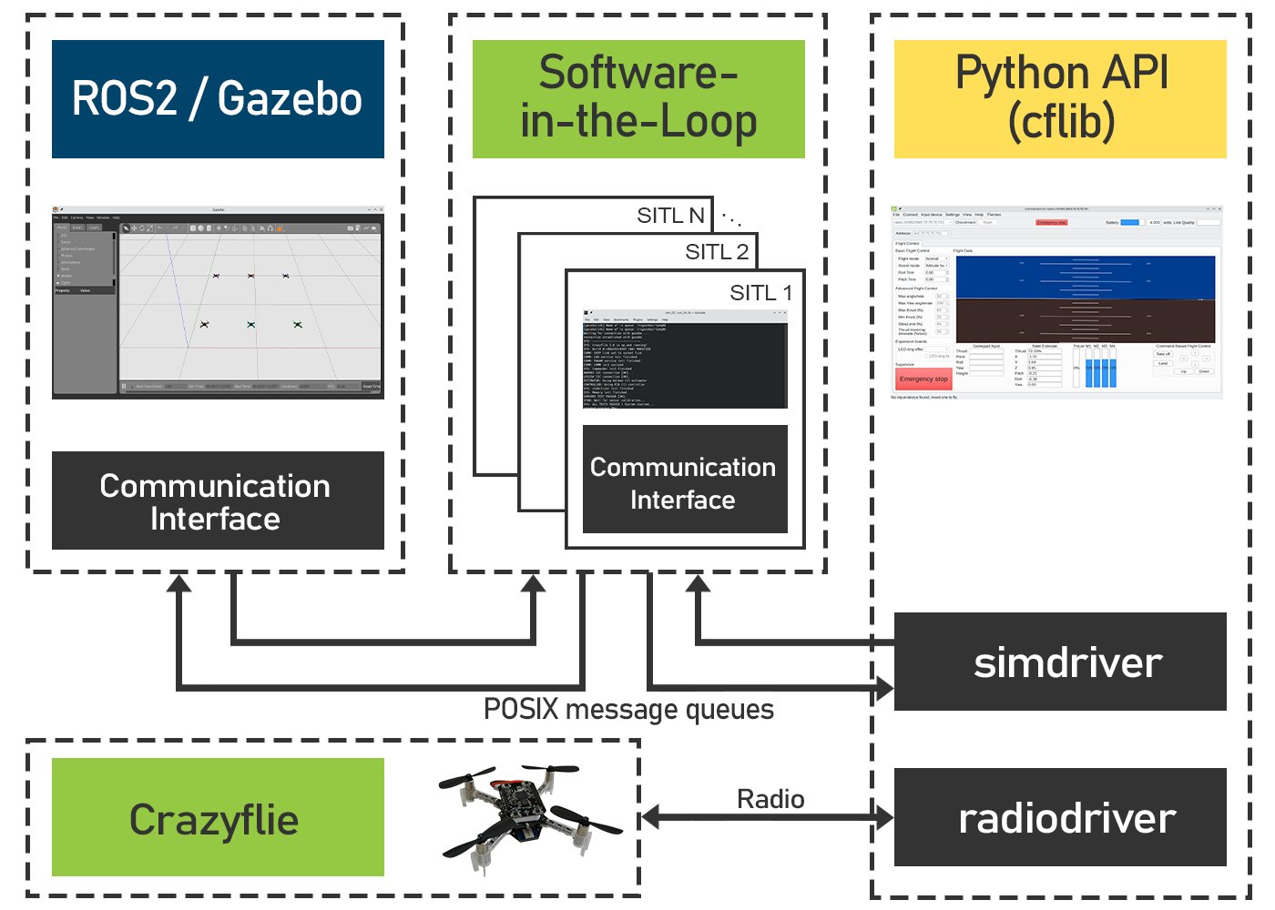
Components of the sim_cf2 Flight Simulator
To run the simulation, the three modules must therefore be started separately. Gazebo is started using the main launch file. The number and initial pose of the simulated Crazyflies is also defined in this file. Once the firmware for the host system has been built, the desired number of SITL instances can be started using the attached script. Finally, a cflib-based script, the Crazyflie client or the multi-agent client presented below is started. With no radio dongles attached to the computer, the simulation driver is initialized automatically and a connection to the simulated Crazyflie can be established.
There are still a few open issues, including the absence of implemented decks for positioning, such as LPS and Lighthouse. Currently, the absolute position is sent from Gazebo to the SITL instance and fused in the estimator. Moreover, Gazebo requires quite a lot of computing power. We were able to run a maximum of four Crazyflies simultaneously on a relatively old laptop. However, a modern desktop CPU with multiple cores allows for simulating a significantly larger number of Crazyflies.
Multi-Agent Client
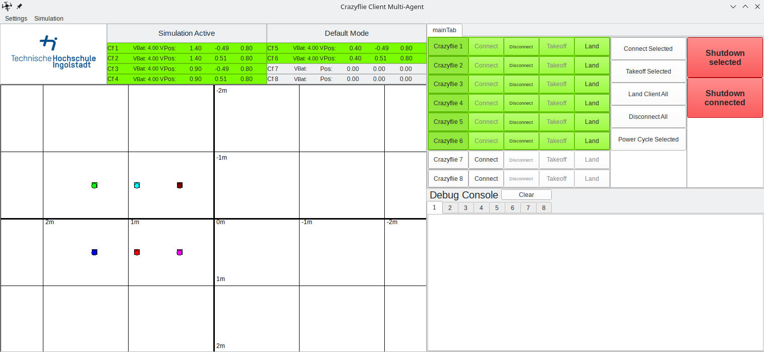
Independent of the simulation we designed a GUI for controlling and monitoring our multi-agent teams. It currently supports up to eight Crazyflies but could be upgraded for bigger teams in the future. So far it has been enough for our requirements.
Multi-Agent Client with six connected Crazyflies
A central feature is the interactive map, which makes up about half of the gui. This is a 2D representation of the flight area with a coordinate system drawn in. Connected Crazyflies are displayed as small circles on the map and a new target position can be assigned by clicking on the map after they have been selected by their corresponding button. If required, obstacles or paths to be flown can also be drawn into the map.
Pseudo-decentralized communication
An important aspect of a truly decentralized system is peer to peer communication. It allows information to be exchanged directly between agents and ideally takes place without a central entity. Currently peer to peer communication is not available in the Crazyflie ecosystem, but is in development.
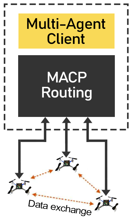
For this reason, we have implemented a workaround in our client, enabling a pseudo-decentralized communication system. This involves adding an additional layer to the Crazy RealTime Protocol (CRTP), which we named the Multi-Agent Communication Protocol (MACP). It consists of an additional packet header made of the destination ID, source ID and a port as endpoint identifier. Every ID is unique and directly derived from the Crazyflie’s address.
These MACP packets are sent via the unused CRTP port 0x9. The packet routing mechanism implemented in the client forwards the packets to their destination. It is also possible to send packets as a broadcast or to address the client directly.
On the firmware side, we have added a corresponding interface to simplify the sending and receiving of macp packets. It is analogous to the CRTP implementation and allows the registration of callback functions or queues for incoming packets on corresponding ports. It can be activated via KBuild.
At least for use in the laboratory and the development of distributed algorithms, this method has proven its worth for us.
Project
We hope that the sim_cf2 simulation can also be useful to others. The complete source code is available on GitHub. Further information concerning installation and configuration can be found in the readme files in the respective repositories.
We would also like to point out that other simulations have been created that are based on sim_cf and therefore offer similar functionality. One of these projects is CrazySim, also available on GitHub. Moreover, there are ongoing efforts to officially integrate such a software-in-the-loop simulation into the Crazyflie firmware and ecosystem.